Skateboard speedometer MK3
(for longboards)
Jonathan Hare, The Creative Science Centre, Sussex University

Please also see the main article for more details Longboard Speedo


MK3 MK3
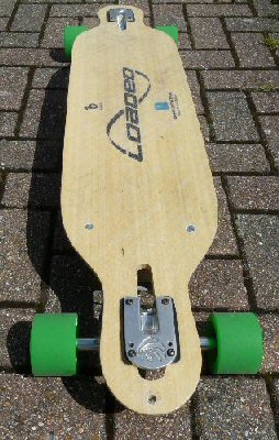
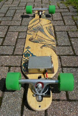
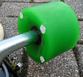
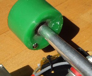
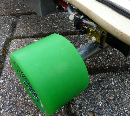
The MK3 speedometer - its not visible from the top but you can see the electronics case under the board.


Please also see the MK1 and MK2 versions

Note: these details of the MK2 and MK3 are 'work in progress', and I will be re-writing them as I have time.

In this version I have reduced the size of the metal box squeezing in as much as I can into something less than half the volume of the MKI. Instead of just using mirrors I have also experimented with other ways of detecting the rotating wheels.

Mirrors, paint and pins
The mirror set used in the MKI worked very well but it was bulky and four screws were needed to secure the assembly to the wheel. I was always worried that the screws may cause the wheel to split over time / use or the unit simply to come off / get damaged.

In this MK3 design I tried using white paint, instead of mirrors to reflect the IR beam. I initially used correction fluid (called 'Tipex' here in the UK) then moved onto white acrylic paint. I painted large blobs about 1cm in diameter on to the side of the wheel facing the IR LED and detector. This worked surprisingly well but unfortunately the continual flexing of the wheel material as you go along caused the Tipex to flake and the acrylic paint to peel off. It lasted about 10 mins. Although the idea was sound the practicalities of trying to paint onto a flexible plastic surface meant it was not reliable.


MK3 paint spots MK3 tack /pin reflector

I tried white paint spots on the wheels to reflect the IR energy. This worked well but the paint flaked off very quickly. Eventually I used a shinny tack (with a long pin) fitted to the side of the wheel. This reflects the IR back to the detector.


I thought of gluing a flexible mirror into the side of the wheel but was worried I might have the same problem with the glue as with the paint. Next I tried using a shiny large drawing pin (tack) which happened to have a long pin length (ca. 1.5 cm). I had to use a clamp to push the pin completely into the wheel but it seemed to stay put. The hemispherical shiny top of the tack reflected the IR beam back to the detector and worked well.

MK3 detector pcb

The IR emitter (transparent looking LED) and IR detector (black square device with dark lens) mounted on a circuit board fixed to the skateboard


detector board and fixing
As in the MKI I used a small pcb to support the IR LED and detector. This was varnished a couple of times to keep out moisture.
I also cut up a plastic box and used two of the truck bolts to secure it in place. The pcb was fixed to this and the whole thing given another couple of coats of outdoor varnish.

Problems
The orientation of the wheel changes as one steers and the IR beam often can't reflect off the diversity of these positions. As a result the speedometer only really logs the speed reliably when going along on straight line, turns can lead to drop-out. The logs therefore provide an idea of the average straight speed along a journey.

Calibration
I used the same techniques to calibrate the MK3 speedo as I did in the MKI. For my wheels I found that a simple x 4.5 multiplication of the logged voltage gave mph. The MK3 is very tidy, small and unobtrusive. It takes up much less space under the board than the MKI. I have also made a better effort to water proof the set-up including the wiring and detector. Typical results
Shown here is a quick spin around a park called The Level in Brighton. The map shows that the total length of the route was about 0.68 mile. The voltage plots show the time for the journey and so the average speed can be estimated from the average voltage logged. From the data below you can see that the trip took about 330 seconds, which is about 5.5 mins which is 1/11 hour. So 0.68 / (1/11) = 0.68 x 11 = about 8 mph. Multiplying each voltage log by 4.5 gives the plot shown below. You can see that the average is close to about 8 mph. The regular small peaks you see all along the data are me pushing the board to keep up a decent speed.


MK3

The logged voltage recorded going around The Level. This has been converted into speed (mph) simply by multiplying x 4.5 (established by the calibration described in the MKI speedometer) The vertical scale is mph while the horizontal scale is seconds (from start). You can see that the average speed was about 8 mph. I've marked various positions on the map (a to g) and I have also included these on the speed data.

Overall then the MK3 is a more robust device than the MKI but I need to work a little more on a more reliable motion detector that can cope with all relative motions of the trucks with respect to the board.
(JPH, June 2011)

More modifications
The paint and the tack (pin) worked but were not perfact. The paint crumbled or peeled off and the hemispherical pin head was too small to accomodate much movement of the trucks while going along. Consiquently the logger was unable to measure all speeds of a typical journey - there were 'drop-outs'. Here I cut-up a small piece of plastic mirror and, using two 1cm brass nails (with fairly large heads), attached it near to the edge of the wheel. This was fairly flat (vertical) and so the mirror is well positioned to reflect the IR beam back to the detector and because the mirror has a relatively large area it can accomodate quite large movements in the truck position.

mirror attached to wheel

Using two brass nails (with large heads + washers) I attached a small piece of plastic mirror cut to shape. The larger reflecting area and near vertical position means it reflects the IR beam better than the paint or tack and so copes with the truck position changes better as we travel around in the board. You can see the IR led (clear white) and just see the IR detector (black). When the wheel turns another 180 degrees it will reflect the IR light from the LED onto the IR detector and produce a pulse. Pulses are averaged into a voltage which can be logged (see the MKI data logger for details).


THE CREATIVE SCIENCE CENTRE


Dr Jonathan Hare University of Sussex, Brighton.
e-mail: j.p.hare@sussex.ac.uk

home | diary | whats on | CSC summary | latest news