Skateboard speedometer MK2
(for longboards)
Jonathan Hare, The Creative Science Centre, Sussex University

Please also see the main article for more details Longboard Speedo


MK2 skate board velocity device

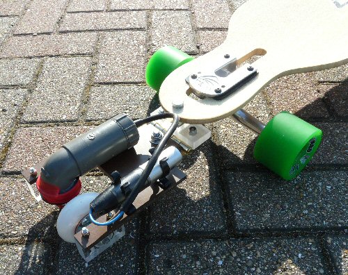
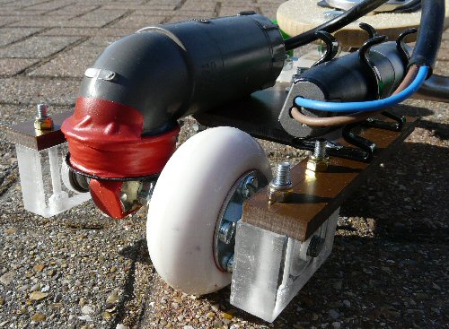
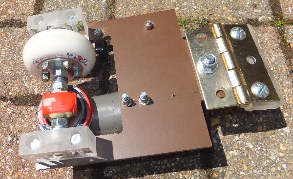
The MK2 velocity measuring device shown connected to the back of the skateboard.


Note: these details of the MK2 and MK3 are 'work in progress', and I will be re-writing them as I have time.

Please also see the MK1 and MK3 versions

Note: let me say right from the start that I don't actually like this version of the skateboard speedometer (which is why there is a MK3 which is much better). I dont like having a device on the back of the board rattling around. This was a purely subjective experience and you may find you are happy. I have therefore continued to include it here because the basic idea is sound and anyway the device may be useful for other ideas and applications.

In the MKI skate board speedo we used an IR light beam to detect the motion of the wheels (using small mirrors attached to a wheel). In this MK2 version we use a fifth wheel to drive a simple generator to produce a voltage. This voltage is proportional to the speed. Like the MKI we can recorded this voltage using a data logger to record the speed while out-and-about. Because we use a fifth wheel to drive the generator the MK2 is probably more suited for a larger skateboard such as a longboard.

In the MKI version the detector electronics needed a battery and the apparatus had to be housed in a box under the board. The MK2 version is actually a simple generator and so produces electricity as it moves along so we don't need to worry about turning it off. Note: the logger has its own batteries so we dont need to worry about powering this.


MK2 skate board velocity device

A close up of the coil assembly (grey tube) and the magnets (half shown covered in red tape) fixed to the axial.
The data logger is shown to the right (top, you can see two wires connected to it).


Generator
The basic electrical generator is a Faraday induction generator. Here a rotating magnet creates a changing magnetic field within a nearby coil of wire. The flux change in the coil creates (induces) an electrical current in the coil. The voltage created in the coil is dependent on the rate of change of the magnetic field (the rate the magnet spins) with respect to time. The coil 'cuts' the flux lines of the rotating magnetic field and this creates a current / voltage in the coil. As this rate of change of the field is dependant on the rate the magnet spins, and this is dependant on the velocity, the magnitude of the voltage created by the coil is therefore proportional to velocity / speed. If we log the average voltage (more below) it will allow us to determine the speed.

Generator description
A roller blade wheel is bolted to an axial which has a pair of strong rare earth magnets attached to it. When the wheel turns it spins the magnets. The axial ends are supported by ball bearing races so that they easily turn with minimal friction. Note: the device will cause a slight drag due to the generator converting movement into electrical power.

Where should it go?
This fifth wheel can either be attached below the middle of the back of the skateboard or it can trail behind like a simple castor wheel on a trolley.

We need to make sure that this wheel is always in contact with the ground and that it won't come away during turns etc. My first attempt to connect the board to the device failed because when I stood on the board it flexed and the fifth wheel lifted off the ground! The device needs to be able to move from side to side (to follow the skateboard) and also to move independently up and down. A simple hinge arrangement and swival joint will do. A flexible sheet of leather used as a hinge would create less vibrations and rattles.

More details of the generator
There are various magnet arrangements that will work. I used a pair of magnets glued and taped onto a hexagonal long-bolt which fits over the axial. When this rotates it creates a changing magnetic flux in the coil. The coil is a circular arrangement of about 500 turns of thin enamelled wire (ca. 26 SWG) having a circumference slightly larger than the area that the magnets will have when they spin around. This coil can't envelop the magnets completely because the axial gets in the way. In this design I just get as close as possible. A coil compleely surrounding the magnets (the axial would pass through the middle) could be arranged but this is more complex and also would be quite close to the ground. In the current design the coil is safely away from being hit by objects on the ground.

I have deliberately chosen a very simple arrangement so that the device is as sturdy and light weight as possible and relatively water resistant. No gearing is needed to simply produce a voltage to log speed but gears could be used if more efficient power generation is required (to power circuits etc. see below).


MK2 skate board circuit

Circuit showing how the coil is connected to the bridge rectifier diodes and the voltage is smoothed by the 47uF cap and 10k load.


Handling the voltage
The generator coil produces an AC voltage as the magnet spins i.e. as the skateboard moves along. The logger can be set to record at various rates but generally not faster than say one measurement a second. As the logger needs a positive voltage we need to convert the AC signal from the coil into a DC voltage and smooth the result ready for logging. To do this we use a bridge rectifier, capacitor and resistor to rectify and smooth the voltage. I built this as a simple 'birds nest' construction, soldering everything together. I used a glue gun to fix and cover the whole assembly to keep the weather out. I used a 47uF (25V) capacitor in parallel with a 10k resistor as a simple load. This will have a time constant of ca. 47 x 0.01 = 0.47 second i.e. about half a second which should respond well to quick changes in speed but at the same time remove the transients that might increase the noise when collecting the data. The logger has a quite high input resistance (100k in my case) and so will be able to make measurements on the resistor-capacitor circuit without loading it greatly.

The device that holds the wheels and coil assembly must also have enough space to support the data logger. I wrapped the logger in a few turns of bubble wrap to try and reduce the vibrations that the logger will have to endure. I used a terry clip to hold the logger inplace but it could have simply been taped or bungeed.


MK2 skate board velocity device - under side

The under side of the MK2 velocity measuring device. You can see the perspex blocks which contain the two sets of bearings that hold the axial. The axial holds the skate wheel and two magnets. The magnets are shown either side of the axial they have been glued in place and covered in red tape. The coil lies below the magnets (red tape covered circle) and is as close as possible to the rotating magnets.

Moving power
The data logger will take very little power, it simply requires a voltage (at a small current). If we want we can use the extra power to do other jobs for us. For example we could drive bright red LEDs which we can use on the back of the skateboard as warning lights. If we smooth and regulate the voltage to control the power we could even imagine charging a mobile phone or other low voltage electrical device (if you go fast enough). This might generate some drag and friction and slow down the skateboard.


MK2 skate board test
Un-calibrated data showing the voltage generated by the MK2 speedometer while skating down the path near where I live. The vertical axis is in volts, while the horizontal axis is seconds from start. I was only doing a few mph but you can see that at decent speed the MK2 would be able to generate enough power to light LED lights or even (with a regulator circuit) provide 5V to charge a mobile (cell) phone for example!

Calibration
As in the MKI speedo we need to find a simple way to convert the logged voltage abd calibrate it into speed. Please see the MKI article for details. When skating around the device creates a few volts (depending on the speed of course) so the logger needs to be able to cope with this sort of input signal i.e. it should be wired into a 0-10V i/p etc.

Downloading and manipulating the data
Once the data has been downloaded it can be transferred onto a spreadsheet for manipulation. Once the calibration has been achieved it is a simple matter to multiply each data log by the scaling factor to create mph or km/h speed plots. Different factors can be determined for mph, km/h, m/s etc.

Problems
As I said at the top of this page I eventually got frustrated with towing something behind me. Also the very strong magnets tend to sweep up all the iron junk around on the roads so you will have to watch out for clogging of the mechanism and regularly clean up the magnets etc.

(JPH, June 2011)

THE CREATIVE SCIENCE CENTRE


Dr Jonathan Hare University of Sussex, Brighton.
e-mail: j.p.hare@sussex.ac.uk

home | diary | whats on | CSC summary | latest news