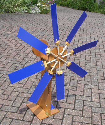
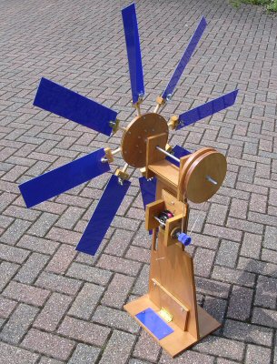
Fig. 1. two views of the windmills showing blades, pulleys, generator and stand
Summary: Described is a simple, cheap and versatile homemade windmill and electrical generator suitable for a school class to explore many aspects and practicalities of using wind to generate electrical power.
Introduction
Living in the UK on an island with limited coal and gas resources but plenty of wind there would seem to be a strong case for the use of wind power. Large scale projects like that proposed for the Isle of Lewis continue to hit the headlines with promises of 'free' energy but possible negative impact on a unique eco system [1,2]. There is a lot of published material as well as internet information [3,4,5]. Wind power promises a lot but can it perform, can you use them anywhere, what are the factors one should know?
Small light weight educational windmills are available but vary in price and usefulness [6] also much has been written about larger structures including workshop information for making 500W turbines [7].
Described here is a simple 8 blade homemade windmill that can be used to explore these issues and generate electricity from wind. There is ample scope for investigations; being able to vary and change the number of blades, their size, angle of attack (to the wind), generator design, and also location considerations. This design is a rugged approach to get you started, it's not a 'state-of-the-art' wind turbine so there is much scope for improvement and innovation by a class. The design is simple and could in principle be made completely from scrap materials at very little cost. Although basic it can be used to drive low power electrical devices such as a small radio.
Types of windmill / wind turbine
Windmills or wind turbines are roughly divided into horizontal and vertical axis types [5,8]. In general horizontal axis mills are the most efficient but need to be steered into the wind. Vertical axis mills work with any wind direction but tend to need some kind of supporting structure around them. A novel and extremely simple vertical axis device is the flutter-gen idea which uniquely might be good for blustery or stormy conditions when other windmills can not be used [9].
Wind Power
Power is energy/time. If we assume that wind consists of a flow of air having mass we can equate this to:
Power P = ½mv² / t
(m = mass of air, v = velocity of air and t = time, ρ = density)
re-expressing this in terms of velocity and mass flow we can get: P = ½v² x m/t
Now mass can be expressed as density x volume and so mass flow is:
ρ x volume / time = ρ x (Area x velocity x time) / time = ρAv
The Area of our simple windmill with blade length r, is A = πr²
We can also assume that our windmill is not going to be perfectly efficient so let's assume its alpha efficient
(0<α<1 corresponding to 0 to 100%), bringing this all together we get:
P = ˝v²ρAv = ˝παρr²v³
so power P is proportional to r²v³ [5]
The power generated by a windmill is dependant on the velocity cubed - if the wind doubles in speed we will get a factor of 8 increase in power!
Further the power will also be proportional the square of the blade length.
Making the windmill
There is great flexibility in the following simple design, none of the dimensions are really critical apart from say a good fit for the axles etc. So please make one to your own specifications based on what follows and have fun playing around with wind power. In principle you should be able to find a lot of what you need in skips, tips and even the strong magnets could be salvaged from old disk drives.
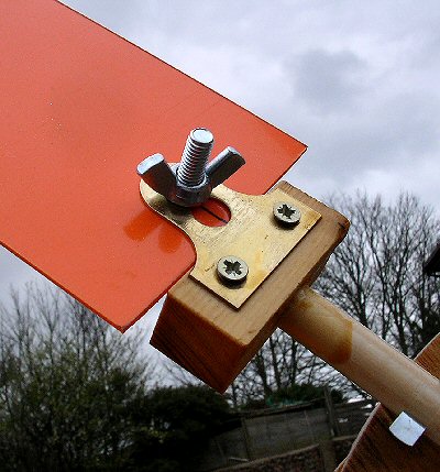
The 8 blades (ca. 6cm x 30cm) were made from sheets of 2mm plastic. A sharp knife can be used to score the sheet, its brakes cleanly and easily. I sanded down the four corners to take away sharp edges. The plastic sheet is fixed to a support via one M6 bolt and butterfly nut. The support was a painting / picture hook bracket fixed by two self tapping screws to a small piece of square cross section wood ca. 1.5cm x 1.5cm x 4cm (Fig. 2a). A 13mm hole was drilled in this to take a tightly fitting round dowel (glued in). The dowels slot into the terry clips on the windmill circle (Fig.2b). The dowel allows easy and quick fitting of the windmill blades as well as being able to adjust the angle of attack of the blades to the wind. Cable ties should be used to help hold the blades once you find your ideal set-up.
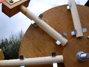
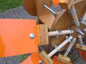
I cut a 20cm circle from 12mm plywood to act as the center hub of the windmill. The center point was carefully marked and the circle was also dividing into eight using a protractor. An 8mm hole was drilled in the center. Also drilled and glued to this center was a smaller 6cm diameter circle. On each 1/8 division line I have placed two small terry clips to hold the windmill blades about 1cm from the circumference and about 1cm from the smaller central circle. This smaller circle provides a stop for the windmill blades, locating them. The hub was fixed at the end of the axial so that under high winds (or gusting) the blades can bend a bit without hitting the stand as they move round.
The circles slide onto a piece of 8mm studding about 30cm long and secured using two large washers and bolts. This goes through a square wooden unit that holds two ball bearings and keeps this axial horizontal. This unit is secured to the windmill up-right by two M6 bolts and butterfly nuts. Nuts are used between the bearings and adjusted / tightened to stop the axle from moving back and forth and stop the axial being sloppy.
On the other end of the axial there was a large pulley which provides drive to the generator. It also helps balance the weight of the front blades and center circle. This is made from two 20cm diameter circles and a smaller 19cm diameter central circle. These are glued together to make a pulley. They are then drilled and slid onto the end of the 8mm studding and secured using two large washers and nuts. It's best to drill all these circles using a pillar drill to get them true.
The electrical Generator
The generator was a very simple AC design and kept as simple as possible so that students can see exactly how it works. The design has advantages in that there are no moving electrical parts to cause problems or become rusty etc. Secondly the generator will work well even when immersed in water [10] so the odd spot of rain while testing the windmill outside will not be a problem at all. A 'black box', off-the shelf motor or generator will no doubt produce far more electrical power if this is required further on in the project.
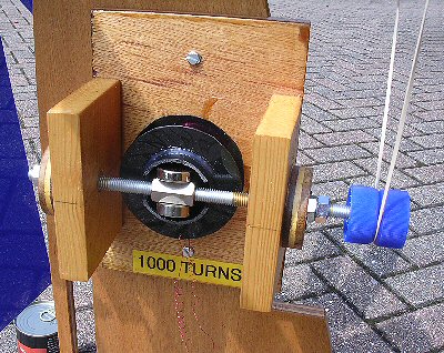
Fig. 3. shows the basic design. A piece of plastic pipe (ca. 45mm diameter) had plastic circles glued to it to form a bobbin for the coil wire. 1000 turns of 35 SWG enameled copper wire were wound within this spool produced by the plastic circles. A hexagonal nut was threaded and glued with lock-tight onto the axial upon which two powerful rare earth magnets (ca. 25mm diameter x 6mm thick) are attached [11]. The magnets are held in place by their own attraction but you might glue them in place once you are happy that they rotate without hitting the sides.
Ball bearing races hold this axial in place and at the end of the axial a simple pulley was made from two bottle tops back-to-back (see photo). A large elastic band acts as drive band to the large pulley powered directly from the windmill.
When the magnets spin they induce AC electricity into the coil windings (more detailed information about the physics of this simple generator can be found in the references below). The voltage produced depends on the rate at which the generator axle rotates. This in turn is dependant on the gear ratio between the large pulley on the windmill axial and the pulley on the generator. So there is a lot of scope for trying out different pulley sizes i.e. different gear ratios.

I designed the generator with a diode x2 voltage multiplier circuit [12] Fig. 4. This boosted the voltage (at the expense of the current) providing about 5V at ca. 50mA depending of course on wind speed etc. This produced a DC voltage suitable to drive circuits and also provided a crude built-in current limit so that if circuits were inadvertently incorrectly wired they were not found to be damaged. Two diodes are used (Schottky diodes provided lower voltage drop than standard silicon diodes) and two 250uF capacitors (ca. 25V) and wired in a simple 'birds nest' type construction and then potted in glue for example to keep out the water / moisture.
The generator was fixed about half way up the up-right on the back under the pulley. A large elastic band connects the two and provides a drive mechanism. Elastic bands provide good grip and allow for stalling of the windmill (the elastic takes up a bit of slack). Large bands are available from stationers. Note: if the windmill and generator axial are not parallel the band tends to slip-off the pulleys after a few rotations. I made the bolt holes on the generator unit a little larger then needed to provide a bit of play so that it can be aligned parallel.
As previously mentioned the generator was designed to show-off the working of electromagnetism rather than to be a state-of-the-art high efficiency device. Saying that the windmill powers buzzers, LED torches and a (3V) radio - providing of course there is a suitable supply of constant wind.
Finally I gave all the wooden parts two or three coats of out door varnish; it makes plywood look lovely and weather proofs much of the mill. Remember to oil the bearings regularly.
Data logging and power load
Maximum power transfer occurs when the load has the same resistance as the output resistance of the generator (assuming a DC source and ignoring power line losses, which in this case are negligible). My generator coil was about 60 ohm but taking into consideration the rectifier (voltage multiplier circuit) diodes I decided to use a R = 100 ohm resistor as a load for data logging the power. Note: varying the resistance to determine the ideal load resistance for maximum power transfer is an instructive set of experiments [13]. I also used a 1000uF capacitor (25V) in parallel with the resistor to smooth the results so that the data logger won't get erroneous results when it takes a snap-shot of the voltage each time it logs.
Electrical power generated by the windmill and absorbed by the 100 ohm resistor was calculated from the logged voltage (V) by:
P = V²/R = V² / 100 (watts) = 10 x V² (in mW).
To get a reasonable idea of the power generated over time I logged each experiment for 15 mins (900 seconds). The data logger measured DC voltage and was set to measure once every second so we had 900 voltage logs. The voltage data was loaded into a spread sheet and then converted into power (mW). In order to get an idea of the average power developed over the 15 mins the 900 power readings were summed and then divided by 900 (seconds).
RESULTS
Number and angle of blades
You can set up the windmill to have 2, 4 or a maximum of 8 blades and see how the power varies with the number of blades. If you use less than 8 then have them opposite each other so that the system is balanced. The relationship of the number of blades, their length and the power produced is more complicated than you might think as more (or longer blades) seem to rotate slower, presumably because of the extra weight (see later).
Also the angle of windmill blade to wind direction (angle of attack) can easily be adjusted to get the most from the wind. 45 degrees might seem like the obvious angle (it did to me anyway) but in fact a much smaller angle is preferred, the ideal apparently being about 6 degree. On reflection this makes sense as then the blades are almost full-on to wind and you are making the best use of the blades surface area. It's amazing to see the improvement going from say a 45 degree angle to 10 or 5 degrees.
Power generation results
Four results are shown here for the windmill mounted about 1 meter above ground in the garden outside my house over 15 min (900 sec) periods. These are Fig. 5.: little wind, Fig. 6.: wind picked up a little, Fig. 7.: windy day but with no constant flow (blustery) and Fig. 8: constant source of strong wind.
What does all this data say?
Firstly the data shows that on a day with little constant wind a windmill at ground level in a garden is almost a waste of time and space. Second on a windy day wind power is very 'pulsed'. So we need a reservoir - some kind of storage device, like a rechargeable battery - in order to realistically run electrical devices.
What's interesting is that despite all the nice looking power peaks the average power - the power that realistically represents what the windmill can actually do for us over a decent period - is really rather disappointing.
The first set not surprisingly has a very small average power, about 0.4mW. The second and third sets have average powers of 2mW and 6mW respectively. 6mW might only power a couple of small LED lights. So even on a quite windy day a garden / household windmill when low down does not provide much useful power. It seems that height and location are very important factors to produce decent powers from a windmill or wind-farm.
It's only when we tend to a near constant wind that we get any kind of usable power to run something electrical. The last data set shows power generated on a day with very constant strong wind. The data was actually obtained in the same location as the other experiments but it might correspond to what you would expect high up, on a hill top or other 'ideal' location. Average powers of 75mW were obtained (peaks of 450mW!). This sort of power can easily run a small radio or charge an i-pod (providing there is constant wind of course).
The interesting thing is that this last data set was obtained using small 15cm blades. Of course the long blades (30cm) worked well but the shorter blades were even better! At first sight this seems strange and seems to go against our power formula we derived earlier, so what's going on?
The simple generator described here is very easy to turn so if you have enough wind you don't actually need much blade surface area. A higher power (generally more difficult to turn) generator would of course benefit from the larger blades as expected. It seems that the smaller blades, being lighter can go round much faster than the longer blades. Voltage is dependant on rotation speed so sometimes the smaller blades can actually work better on a low torque generator - provided of course you have enough constant wind.
It should be apparent now that there is a wide range of interesting and topical experiments and investigations that a class (or science club) could undertake with this simple windmill and generator design. After spending the summer traveling around the UK with three of these I can also say that they are great fun and I have learnt a great deal from them - I hope you do too.
Acknowledgments
I would like to thank Emily Unell and all at the Open University BLAST ! team as well as all the Rough Science TV crews and also the Vega Science trust (Sussex University).
References:
[1] The Battle of Lewis, The Independent, Saturday 26th January 2008
[2] See also the BBC TV Coast, series III, Isle of Lewis program.
[3] Using wind power, National Wind Turbine Centre. ISBN 1 870064 19 4
[4] Wind Farms in the UK, The British Wind Energy Association, Paul Hannah, 1996. ISBN 1 870064 26 6
[5] e.g. see: http://en.wikipedia.org/wiki/Wind_power
[6] for reviews see:
Kinchin J. Phys. Educ., 2005, Vol. 40, (No. 6), 588 – 589 and
J. Kinchin J. Phys. Educ., 2006, Vol. 42, (No. 2), 574 – 575.
[7] Windmill Workshop, Hugh Piggott, 2000. ISBN 1 898049 27 0
[8] See also the Vega Trust mini movies - Three Windmills, by J P Hare:
www.vega.org.uk (go to educational resources)
[9] Sharp-Hare Flutter-gen:
www.creative-science.org.uk/sharp_flutter.html
[10] See the sixth series of the BBC TV Rough Science where we made a water proof generator to go down a mine.
Alsoe.g. see http://www.creative-science.org.uk/rshandgen.html
[11] Suitable Rare Earth Neodymium Magnets can be brought on e-bay.
[12] Voltage multipliers URL: e.g. see http://www.creative-science.org.uk/multipliers.html
[13] Using dataloggers to measure the power output and efficiency of wind turbines, J Kinchin and S Boyns J. Phys. Educ. 2007, Vol. 42, (No. 2), 122 – 124
NOTES:
[a] I designed the windmill for the Open University out reach group - BLAST !. We used it as a traveling children's workshop as part of the COAST TV series Roadshow. The windmills have been tested on-the-road in over 10 major cities around the UK by 100's of kids. The participants had to assemble the blades, chose the best angle and use the windmill / generator to power a buzzer (easy), torch and treasure box. The treasure box had an LCD screen that printed out where the key was to open the box for the treasure (chocolate!) but they needed to power the electronics for 10 seconds in order to read the (deliberately) slowly scrolling screen. Finally when the whole set up was working to a maximum they could power a small radio.
[b] The BBC TV Coast, series III, went to the Isle of Lewis. There are two very nice short clips that teachers can use from this program. The first discusses the tremendous power available in such as windy location, while the second discuss the environmental and personal impact the wind farm would have on the island and their peoples.
[c] If you find the generator does not produce much voltage it's most likely due to not having strong enough magnets. You need to use the very strong rare earth Neodymium Magnets (ca. 20mm diameter, 6mm thick) which are available on e-bay for example or you maybe you could use scrapped hard disk drive magnets.. Take care when two of these are close together as they can jump together and can nip / cut skin if a hand is in the way.
[d] The generator design is similar to one made for the Colorado series of Rough Science which was used to make electricity down a wet mine. To test it out I showed it working perfectly in a bucket of water, so it should even cope with the British weather!
[e] I used a professional Testo 175-S2 data logger (0-10V input) for data logging the voltage from the diode multiplier circuit but Lascar Electronics produce a very reasonably priced logger (EL-USB-3) that is ideal for these sorts of investigations.
The following URL's might also be useful:
shake-a-gen page
storage device page
voltage multiplier page
6 gens page
Natures Power page
Vega module film clip of three windmills (including the 8 blade mill shown here)
THE CREATIVE SCIENCE CENTRE
home | diary | whats on | CSC summary | latest news