
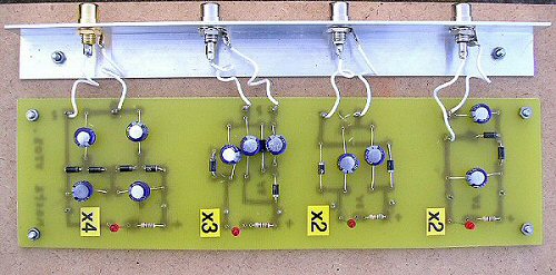
A circuit for a x2 multiplier
Four circuits are shown: two giving x 2, x 3 and x 4 multiplication (and rectification, DC) of an AC input voltage.
Of course, they don't magically multiply the voltage, its at the expense of the current that can be delivered at the output, which drops accordingly. So for a given power input P = V x I, P=power (watts), V=Voltage (volts) and I=current (amps) as we multiply the voltage by x3 to get say 3V then the current drops by a third to I/3 (ignoring losses etc.). Note: that if you are only drawing a very small current (say from a meter) then you can multiply the voltage very effectively but if you are trying to power a circuit that takes much more current then you may be limited in current before you even start to multiply the voltage - in this case the experiments will fail and no apparent mutiplication of the voltage will be observed.
If you are using these circuits from a high frequency voltage source (kHz - 100kHz) then small signal 1N4148 diodes will work better than the slower silicon rectifier diodes (e.g. like the 1N4002 presumably due to their relatively high junction capacitance). For high voltage but low frequency circuits (50 or 60 Hz) the IN400X series work well.
Note: NEVER use these ladder circuits directly on 240V mains supply.
Note: The last number of the silicon diode code / marking is the PIV (peak inverse voltage) - which is the brakedown voltage the diode is rated to (where X is the PIV divided by 50, i.e. 1N4001 is a 50V PIV diode,1N4004 is 200 V PIV etc.).
For low voltage experiments such as with the shake-a-gen you dont want to use normal silicon diodes as 0.6V will be lost as a voltage drop across each diode. In these experiments germanium diodes (e.g. OA91 etc.) can be used or better still schottky diodes - both have very small forward voltage drops (and so far less loss in a low voltage circuit). Note: germanium diodes are only suitable for low voltages and can not carry much current (ca. only mA's but probably ok for powering an LED).
HOW THEY WORK - the first circuit as an example
Something like this ..... in the first (voltage doubler) circuit when the AC input is negative then D1 is ON and the first capacitor C1 charges up with the polarity shown (-V). When the AC input goes positive D1 turns OFF and D2 turns ON charging up C2 with the series sum of the voltage on C1 (V) and the input voltage (also V). This gives C2 a voltage of V + V = 2V. D2 blocks voltage on the negative cycle and simply charges up the first capacitor C1. The voltage on C2 is also the output circuit and so the voltage on the output is 2V, we have doubled the input voltage, the output is now 2V DC.
Typical starting values will depend on the frequency of the AC voltages. For the shake-a-gen (very low frequencies) try using 10V, 220uF electrolytic capacitors (watch the cap polarity as shown in the circuit diagrams) and 1N5819 schottky diodes. A typical load might be a multimeter and / or a low current, high brightness LED and a largish series resistor (say 1.5kΩ) to limit the current. You can have fun experimenting !
Thanks to John Wagner in Houston for spotting an error on the x4 circuit.
THE CREATIVE SCIENCE CENTRE
home | diary | whats on | CSC summary | latest news