link to 6 gens page

ROUGH SCIENCE HAND CRANKED GENERATOR

What follows are some notes on making a hand cranked generator that can power a string of LEDs or small bulbs and could be used to power a radio or charge a mobile in emergency situation. In the Rough Science TV series prototype I used a tape measure spring to drive the mechanism so I didnt have to keep winding the handle all the time. Note: I havent included much detail here as nothing is very critical ... its up to your imagination to work out your own version :-) the notes on the other generator page (see link above) will be helpful for those wanting to understand the theory / how it works.


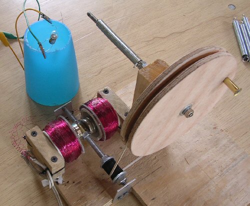
hand gen


The Rough Science hand-cranked generator showing the induction coils (each 1000 turns of thin (e.g. 25-30 SWG) enamalled wire), magnets (x4) and the homemade gear mechanism / crank (far right). Two magnets, one either side of the crank shaft will work well but if you have space then you can double up to 4 as I have done here to get more electricity. The magnets are so strong that they hold themselves in place by the magnetism.

Note: you need to use the rare earth magnets (iron or ceramic magnets wont produce enough field strength, see the shake-a-gen article for more details (above link). Two nuts in the middle of the (studding / thread) shaft allow the magnets to be positioned properly - the magnetism holding them in place. The coils need to be positioned as close to the rotating magnets as possible.

How much voltage can we generate? To a rough first approximation the voltage (V) generated by the set-up is proportional to the strength of the magnets (M - tesla) and the rate you spin them (dM/dt tesla per sec), the area (A - m2) of the coil(s) and the number of turns of wire (N), so V = N x A x dM/dt so if you have N = 1000 turns, magnet surface strength (for 1 magnet) = 1 tesla, rate of turning = 5 turns a sec (so dM/dT = 5 tesla / sec), area A = 0.001m2 then V = 1000 x 0.001 x 5 = 5 V (peak).
Note: that the voltage induced in the coils will be an AC signal.

If you use more magnets and two sets of coils you can generate more voltage (see below). As the coils of wire need to interact with the moving flux from the rotating magnets the coils should be as close as possible to the magnets. So in a very large coil you wont get the increase you might expect as many of he turns will be too far away from the magents. Also the internal resistance of all that wire will limit the responce. 500 to 1000 turns works ok but you will need to experiment in order to 'peek' the responce for maximum efficency for your particular set-up.

With two sets of coils you need to make sure the coils are correctly wired together. By correctly wiring the coils (two wires on each coil) in series you can add the voltage created in each coil. By correctly wiring the coils in parallel you can add the current. Incorrectly wiring the coils will cause the current / voltage to cancel. If you use two coils the first wire of the first coil will be one terminal of the generator. The second wire of this first coil is then joined to the first wire of the second coil (remember to scrape off the insulation and once happy it is working properly then solder the wires together). The final wire on the second coil then forms the other terminal of the generator. You cant do much harm getting this wrong but obviously you need to get the wiring correct for best results.


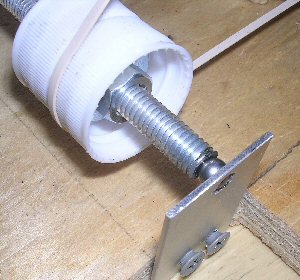
hand gen bearings


The simple ball bearing mechanism used to reduce friction. The balls came from an old bicycle wheel while the axal is simply a piece of studding drilled at the ends to make an indentation for the ball to sit in. A sheet of metal with a small hole to locate the ball applies tension to the assembly. A drop of oil and the thing spins very nicely.


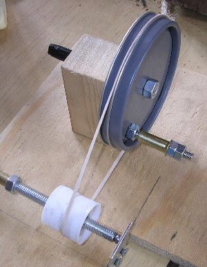
hand gen gears


An earlier version of the simple gearing. A single turn of the handle rotates the magnets many times with this simple gearing. This means that the magnets can get up a good speed between the coils to induce as much voltage as possible. The grey gear is made from two coffee lids bolted together, while the white 'gear' is made from two water bottle caps fitted back-to-back (held in place with nuts). The ribbed edge of the caps gives a good grip to the rubber band. A slightly smaller tube-of-glue cap was eventually used in the final design (shown in black in the first picture above)


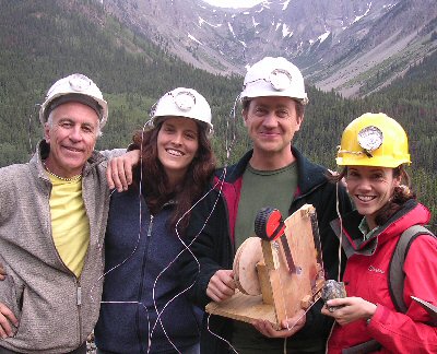
RS crew near mine


At a steady pace 8-10V at 200-300mA was possible, enough to light 4 or 5 small torch bulbs. These were wired to hard hats and used as mining lamps. With this gear we investigated a Colorado mine. I took a tape measure apart and used the internal steel spring to power the generator. Winding up the generator one way produced electricity but also wound-up the tape measure spring. On releasing, the energy stored in the spring powered the generator as it un-wound. Repeating this procedure gave us continious light without me having to spend all my time cranking the handle.


Note: as this simple design has no moving electrical contacts it is safe to use in wet conditions (I tried it completely immersed in a bowl of water and it worked a treat!) and also where there may be explosive gases such as down in a poorly ventalated mine shaft.

Details of the electrical theory of the generator can be found on the 6 gens page:
link to 6 gens page
link to RS6 page

THE CREATIVE SCIENCE CENTRE


Dr Jonathan Hare, The University of Sussex
Brighton, East Sussex. BN1 9QJ

home | diary | whats on | CSC summary | latest news