|
6 generators page |
magnet notes |
hand cranked gen |
AC to DC |
more soon |
back to 3D page |
|
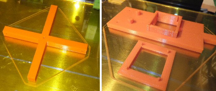
4-way cross 4 way.stl file 4 way.g file 4 way.scad file |
main and coil 3D .stl file 3D .g file 3D .scad file |
base 3D .stl file 3D .g file 3D .scad file |
3-way cross 3D .stl file 3D .g file 3D .scad file |
more soon |
back to 3D page |
The 3D printer has a distinct advantages over making the device by hand. For example the shaft channel that takes the 3mm threaded bar on the main 3D printed device is not an easy thing to drill accurately parallel but the 3D printer of course simply lays down the plastic creating a perfect channel. With a 3D printer you can print out as many versions as you need to, to get a really perfect fit for the particular magnet you intend to use. This is easier for a beginner to do using software (which can be adjusted to an acuracy of ca. 0.1mm) rather than trying to make everything new by hand.
modifications / hints and tips
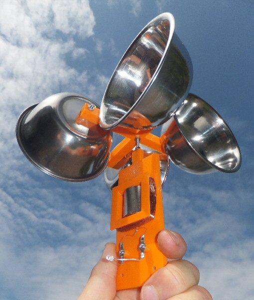
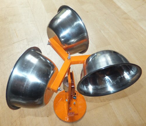
The cross piece that holds the cups will rotate when the wind interacts with the cups. The cup orientation will determine the direction of rotation (irrespective of the wind direction). It does not matter which way the generator turns but the wrong rotation direction will tend to unscrew the nuts holding the shaft! So you need to make sure the cups are the correct way around (you can work it out by trail and error and the photos will help). I put a bit of thread-lock glue on the nuts at the cross piece.
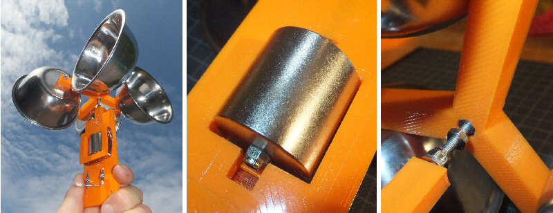
The magnet sits very neatly into its square hole. You have to fit it in place and then carefully screwing in the thread from above while holding the top nut in place above the magnet. As the thread goes in it will eventually emerge from the bottom of the magnet and you can then add the final nut (its a bit tricky). I applied thread-lock glue to the nuts and also into the shaft going through the magnet.
Once the magnet is in place you can pop on the square coil former via the four 3D printed pins that locate into the 'chimney' on the other piece. A dab of super glue on the pins will help. Then wind on the wire in the bobbin that has been created. I used 500 turns of 35 SWG wire in the prototype. The internal resistance of finner wire will we greater and so you will get greater power loss. However if you just want to use the device to show the principles of wind power to simply light an LED for example, a 1000 turn coil (easier with finer wire) will light the LED with less wind speed.
Once the magent is in place and coils wound, you can fit the 4-way (or 3-way, see below) cross piece on the shaft and see if it all turns ok. You might have to adjust the nuts around the magnet and the nut that holds the shaft at the top of the main 3D printed unit. A little light oil in the shaft channel will make it rotate easily. You can simply wire in an LED to the two coil wires or wire up a rectifier and capacitor to create a DC output (see links in table).
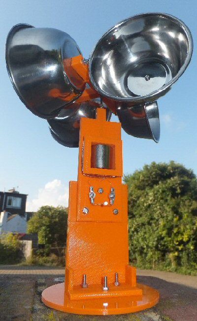
In the bottom couple of photos you can see a 3D stand I made so that it can sit on a table - you can use it as a demonstration model etc.
I noticed that the 99p shop near me stopped selling the cups for a while. They have now brought them back but in packs of three not four ... they also seem thinner. I guess I am the only person who is actually happy about this, as the lighter they are better! So I have built a 3-cup version. The 4 cup may have more power / torq. than a 3-cup but the later will probably spin faster. The simple coil-magnet generator is a 'velocity' device - in other words the faster the rotation the greater the voltage - so the faster speed is better. I also built-in a counter sunk hexagonal hole into the 3-way cross piece. This makes it much easier to get a tight fit to the shaft.
You can see in the last photo (bottom of the page) that the coil lies to one side of the center of the magnet. In principle you can add another coil set to the free side to double the power (wire the coils in series but be carefull about the phase / wiring otherwise the voltages will cancel instead of add). Note: it may be much more difficult to directly 3D print a double coil and you might simply make another piece that can be fitted on.
In this very simple design the cups are connected directly to the magnet. As the generator creates a voltage proportional to the speed the magnet rotates it would be a good modification to use a pully system drive from the shaft to the magnet to speed it up. This would of course make the design more complex and less robust but it would mean that you could in principle create more voltage at lower wind speeds (provided the gearing does not stall the movement of course).
I plan to record the AC voltage created by the generator for different wind speeds (against a calibrated wind speed meter) so that we can make this simple wind powered generator into a working anemometer. Watch this page ....
THE CREATIVE SCIENCE CENTRE
home | diary | whats on | CSC summary | latest news