Notes on coil-magnet orientation and rotation


An electrical generator is in essence a very simple device - magnets rotating within a coil of wire*. To get a generator to work properly you need to make sure the coil and magnet orientation and rotation are correctly aligned. I have developed a number of simple generators (see links below) that are receiving enthusiastic e-mail enquiries and questions from people all over the world. Eventually the subject of magnet orintation / rotation comes up so I have written these notes to help clarify the basics.
(* or coils of wire rotating around a magnet)

Links to relavent pages on this site:
* six generators
* Large search coil MK I
* Large search coil MK II

Please note: these generators are delibrately simple designs (thet dont have soft iron cores and other basic refinements for example). They are not ment to be state-of-the-art but devices that can get you started exploring electricity generation.

Magnets and their fields
If you place a magnet under a piece of paper and then sprinkle iron filings on top, a careful flick of the paper will align the small particles and reveal the beautiful magnetic field lines or magnetic flux. The lines approximately show the 2D cross-section of the 3D field originating from the magnet. The development of computer hard-drives and other technology has meant that the strong so called 'rare earth' magnets have become cheaper and easier to obtain. These magnets produce much greater field strengths than the 'strong' magnets from a decade or so ago. If in doubt try to use the rare earth magnets for your experiments. These magnets come in many shapes, sizes and forms. Most are straight forward to use. Below we see the arrangement of the poles on various types of magnets. The right hand magnet has an unusual pole arrangement.

gen coils
Fig. 1. Various magnet types and magnetic pole position. Usually the N and S pole are at the ends but this is not always the case. For example the spherical magnet has no 'ends' but can be made with N and S poles opposite each other. The right hand device is an example of a magnet with an unusual pole arrangement where the N and S poles are at the sides rather than the ends. This can be used to advantage in simple generator designs (see below).

For a bar or disc magnet the lines appear to come out of one pole (located at the ends or faces) and circle around to the other pole. If you spin these magnet around a line joining the two poles the pattern hardly changes, you might not even realise that the magnet was spinning under the paper. However if you spin these magnet at right angles to this axis (the N and S poles tumbling over each other) you would see that the whole pattern would try and follow the movement. Although in both cases the magnet is rotating the effect to an observer looking on is dramatically different. If a coil of wire is arranged around the rotating magnet what happens in the coil will also be dependant on the magnet axis orientation and rotation. This is important for our understanding of how to make an efficient generator.

Faraday Induction
In order to generate as great a current and voltage into a coil of wire one generaly needs the coil to be as close as possible to the magnet so that it can interact with as great a part of the magnetic field as possible. Further to this the coil must interact with a changing magnetic field as the electricity generated in the coil (induction) is due to the rate of change of field strength, not the static strength.

The size, position and shape of the coil, as well as the type of magnet, its orientation and axis of rotation are therefore important. For best electricity generation (maximum induction) you want the coil to interact with as great a rate of change in magnetic field / flux as possible.

If we spin the magnet around the wrong axis (which depends on the pole arrangement of course) the coil wont see a large changing magnetic field irrespective of the apparent motion and stength of the magnet. If we take the basic disc magnet (shown second from the left Fig. 1) and spin it as shown in Fig. 2a or Fig. 3a it wont effectively produce electricity. If we rotate the magnet so that it moves around the axis at right angles to this (e.g. Fig. 2c, Fig. 3b and Fig 4) it will work well.

coils and magnet orintations
Fig. 2 generating electricity is not just a case of simply spinning magnets in any direction within coils of wire. The magnets need to be aligned correctly relative to the coil and the magnets need to be spun correctly. Three posibilities are shown here. Only the third diagram will effectively generate electricity in the coil when the disc magnets are spun.

Going back to the iron filing experiment you can now see why the particular direction and orientation of the magnet rotation matters. In the first two cases, Fig. 2a and 2b the magnet rotatation is such that the coil experiences no change in field strength (so the filings dont move around much) and so no electricity is generated in the coil. In the other example Fig. 2c the magnet rotation causes maximum change of field in the coil as the magnet rotates (the filings move about) and so electricity will be created.

So in Fig.2a the magnet spins around the NS axis so as it rotates the field lines that the coil experiences don't change with time. The case in 2b is not so obvious but actually although the magnets are now no longer rotating along the NS line the coil is not aligned correctly, so again their is little or no change in field through the coil. The rotation of the magnet in Fig. 2c, Fig. 3b is such that every turn of the magnet produces a large change of field in the coil.

gen coils
Fig. 3 shows diagrams of a simple generator using a disc magnet. Only the right hand version will generate electricity correctly.


Fig. 3 shows the incorrect and correct way the disc magnets should rotate for the particular coil shape and position shown. A very simple demonstration generator following these principles is shown in Fig. 4 and you can see the details at the following link:
* pipe gen

pipe gen diagram pipe gen
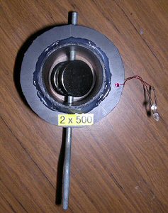
Fig. 4 The same generator as described in Fig. 3, its circuit diagram and a photo of a working prototype on the right. Two rare earth disc magnets are attached (by their magnetic attraction) to the crank. When this crank is turned the changing magnetic field induces electricity in the coil. A coil of a few 100 of turns of wire and a pair of strong rare earth magnets, turned a few times a seconds, will create enough electricity to light a couple of LEDs. If the two LEDs are wired in opposite directions (see circuit diagram) the AC nature of the generator voltage shows itself - the LEDs alternately light as the crank turns. One LED lights for each half turn (half cycle) of the magnets.

gen coils
The generator in Fig. 4 works well but arranging the magnets is a little fiddly. I used the magnetic attraction between the two disk magnets to secure the magnets either side of the crank handle. You can glue them in place to make them secure. Looking back at the various types of magnet avaliable the one shown on the right hand side of Fig. 1 can be used to make things even simplier. So just to show that you always have to think about the type of magnet you are using Fig. 5 shoes an arrangment very like that shown in Fig. 3a which for the disk magnets would not work well. However here we use a unusual cylindrical magnet that has its poles at the side of the cylinder, rather than at the ends. In this case when the magnet is rotated it will create electricity in the coil around it. It is actually equivalent to Fig. 2c, Fig. 3b and Fig. 4. The only awkward thing is that the magnets I have seen like this tend to have a very small hole going through them so the shaft is a bit thin, so you have to work around this.

The simple shake-a-gen
For the very simple shake-a-gen the best magnet motion would be when the magnet spins around within the coil but this motion is very hard to create simply by shaking the can up and down! (Fig. 6) However shaking the magnet up and down will still create a large change in field through the coil and thus still generate voltage / current pulses - enough to light the LED (if you have a strong enough magnet or enough turns of wire on the coil), Fig. 6.
* shake-a-gen

gen coils
Fig. 6 The simple Shake-a-gen - the disc magnets move within the coil simply by shaking the can. The two scinareos shown in Fig. 4b will actually work but because the coil is too large (or the magnet too small), or the orintation is not ideal, the coil only sees a small proportion of the changing flux. So the two examples of Fig. 4b wont generate as much electricity as Fig. 4a or 4c.

n turn coils
In principle the number of turns of wire (n) multiplies the voltage induced in the coil so the greater the number of turns the greater the voltage. However if you have too many turns the coil becomes very large which means that the total length of wire is great. This will mean a high overall wire resistance and so losses. Also because the coil is larger parts of the coil are no longer so intimately associated with the magnetic field being further away. So there is a trade off: small wire mean that many turns of wire can be wound close to the magnet but the coil will have high losses (resistance), while thicker wire will have less loss but less number of turns are practical.

Last thoughts - common problems
If you use thin enamelled (insulated) copper wire for the coil windings, remember that you need to scrape off this insulation at the two ends to make a good connection to the copper wire. Ideally 'tin' the ends of the wires i.e. you put a coat of solder over the ends to maintain a best connection to the coil (bare copper soon gets dirty). The heat and solder flow from a soldering iron can burn-off the enamel. You need to start of the very end of the wire, where there is a small bit of pure copper revealed at the cut-off. If you start from there it just takes a few seconds for the enamel to burn-off, then you will find the solder starts to flow nicely down the next 3 or 4mm of wire.

Once good connections have been checked a generator usually fails to work properly because people are using magnets that are too weak for these simple generator designs.


CHECK LIST
* make sure the magnets are the (very strong) rare earth types
* make sure the coil is a close to the magnet as you can get it (while still allowing the magnet to rotate of course)
* confirm that the coil arrangement and magnet spin orintation are correct for your magnet
* clean and solder ('tin') the two ends of the coil wires


THE CREATIVE SCIENCE CENTRE

Dr Jonathan Hare, The University of Sussex
Brighton, East Sussex. BN1 9QJ

home | diary | whats on | CSC summary | latest news