SEPnet coil demonstrates electricity generation
Clare Harvey* and Jonathan Hare**
* Physics Department, Surrey University
** Creative Science Centre, Physics Department, Sussex University
Note: this article has been published: C. Harvey and J. P. Hare, Phys. Educ. 44 (2009) 603-606. reproduced here by permission of the IOP
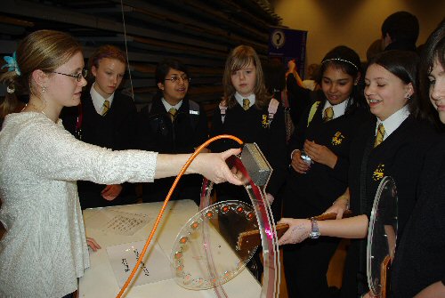
Pupils discovering how to make electricity ... but how well would this work?
The South East Physics Network (SEPnet) [1] is exploring various ways to enhance physics learning and A-level uptake, including a series of interactive GCSE revision events. The first event, which includes talks and various physics exhibits by leading teachers and educators, is on energy and the exhibition - "who will keep the lights on?"- is traveling around southern UK venues. Here we describe the demonstration that shows how electricity is generated.
Generating electricity
The main way electricity is generated is by Faraday induction: The induced electromotive force (EMF, voltage) in any closed circuit (e.g. coil of wire) is equal to the time rate of change of the magnetic flux through the circuit (see below for discussion of magnetic flux). Faradays law in terms of magnetic flux (φ) is given by:
V = - dφ/ dt
A voltage is created in a search coil by a changing magnetic flux, or equivalently a voltage is generated in the coil (in a static field) when the coil is picked up and rotated. The magnitude of the voltage induced in a coil of wire of Area A (m²) with N turns experiencing a time varying magnetic flux density of dB/dt (in Tesla / s) is:
V = N x A x dB/dt
Many school based demonstrations are based on a small coil or dynamo which can be difficult for a larger group to appreciate. So we decided our simple demonstration would use a large coil, large clear meter and magnets attached to a hand held paddle. As it has been built quite large it's easy to see what each part does and also can be clearly seen by an audience gathering around. Robust construction means people can pick up different magnetic paddles and also the search coil to investigate Faraday induction for themselves.
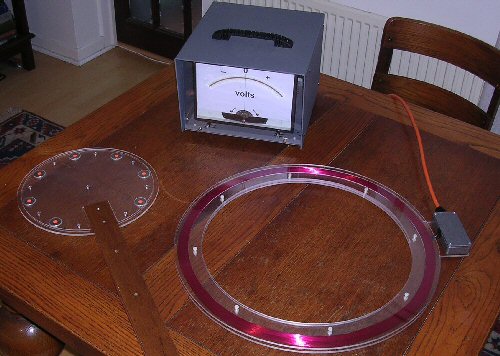
Large search coil specifications:
* N = 1000 turns of 34 SWG (ca. 0.25 mm) enameled (insulated) copper wire
* average coil diameter ca. 50 cm, so Area A ~ 0.2 m²
* total resistance of coil R = 600 Ω
* total length of wire ca. 1.5 km
* clear Perspex coil frame
Meter specifications:
* fitted into strong metal box with protective Perspex screen
* large centre-zero voltmeter ± 250mV FSD
Magnetic paddle specifications:
* Large 30cm Perspex circles holds neodymium magnets
* Paddles with 2, 4, 7 and 13 magnets (24 mm diameter, 5 mm thick)
* wooden handles to facilitate magnet manipulation
Voltmeter v ammeter
Ideally an ammeter should have zero internal resistance but in practice the sensitive meter windings will have quite a lot of very thin wire which will have quite a high resistance. This means that when a current flows voltage will be dropped across the meter. For small signals this effectively makes the micro ammeter into a milli voltmeter. Our meter resistance was 1800 Ω, which (by Ohms law) means you need ca. (V = R x I = 1800 x 140 / 1,000,000) ∼ 250 mV to get the 140 μA meter to give a full scale deflection (FSD). With no extra series resistor our ammeter thus works as voltmeter reading ± 250mV FSD. The meter resistance is substantially higher than the internal resistance of the search coil so there is little 'loading' by the meter.
Two silicon diodes were wired back to back across the meter. These will only conduct above 0.6V and so provide some meter protection from large voltages that might be generated in the search coil.
Experiments 1 - The earth's magnetic field
In the UK the earth's magnetic field is about B = 50 μTesla [2]. If there are no magnetic objects around to disturb the field it will be very uniform over the search coil. By picking up the coil and rotating it backward and forward every second or so, the earth's static field will appear to be changing in the coil at a rate of about:
dB/dt ∼ 50 x 10-6 / 1 ∼ 0.00005 Tesla / s
If we get the alignment correct this will generate a voltage in the coil by Faraday Induction, and from the first equation we can estimate that it will be:
V ∼ N x A x dB/dt ∼ 1000 x 0.2 x 50 x 1 / 1000000 ∼ 0.01 V ∼ 10 mV
In practice we find the meter only moves a little, about a 20th of the scale but this corresponds to about 250 / 20 ∼ 13 mV so its about right! So without having to have any complicated electronics, just a large coil, we find we have a very basic magnetometer capable of detecting the strength of the earth's magnetic field! (Note: a compass only shows the direction).
Experiment 2 - Field from the magnetic paddles
Modern rare earth (neodymium) magnets are now quite cheap and widely available (e.g. e-bay). They have surface magnetic fields 1000's times that of the earth's field. So you might expect from the above that moving such a magnet through the coil would produce ∼ 10V. However we soon discover that we don't get anything like this. Why not?
If you could get a magnet almost as large as the coil, say 50 cm across then it would work. However our magnets are just 2.4 cm in diameter. If we cover a magnet in a sheet of paper and sprinkle on iron filings we see that the filings align themselves. The filings allow us to see some of the magnetic flux lines emerging from one pole of the magnet, going out to some distance and then looping back to the other pole.
A coil of wire surrounding the magnet will have electricity induced into it by the change in magnetic flux through the coil windings. As we have seen this can be done either by a correct change in the position / orientation of the magnet or of the coil.
However, we can see that with a large coil and a small magnet, only the more remote field lines will interact with the coil windings and as this only represents a small amount of the flux from the magnet, the induced voltage is proportionally lower. In other words many of the flux field lines emerging from one pole of the magnet loop back to the other pole without ever interacting with the coil which, in this case is much further out.
Very large magnets are not available (and would be fragile and very expensive) so in order to overcome the short-fall of the single magnet we have attached a number around the circumference of the circular plastic paddle. Each magnet was marked on the surface with a red spot sticker (by convention the pole with a red spot is the one that, in a compass, turns northward over most of the earth [2]). Paddles containing 4, 7 and 13 magnets were constructed and used as a moveable / changeable magnetic field to stimulate the search coil.
Even on the paddles (where there is more than one magnet and these are quite near to the coil) the voltage does not increase as much as one might expect. This is because the coil windings are only on one side of each magnet so much of the flux from each magnet never interacts with the coil and so does not contribute to electricity generation in the large coil.
Discovering Faraday Induction
For sensible movements of the paddle one can easily make the meter go almost FSD (0.25V) with the 13 magnet paddle. Less numbers of magnets produced proportionally less signal as expected.
Using these magnets we can show various principles of Faraday Induction. As the magnets are brought towards the coil it interacts with more magnetic flux so dB/dt is say positive and we get a corresponding reading on the meter. We get a 'positive' pulse the strength of which depends on the speed at which the paddles are brought near to the coil.
If we leave the magnetic paddle in the centre of the coil the magnetic Flux strength is strong but the flux is NOT changing and so dB/dt = 0. Hence the meter stays at zero and does not move. If we now remove the magnets dB/dt is negative and so we get a similar but reverse reading on the meter as we did when we introduced the magnets. We get a 'negative' pulse. The exact direction of the meter movement will depend of course not only on the rate of magnet movement but also on the orientation of the magnets relative to the coil, i.e. whether they are 'red spot up' or 'red spot down'.
The magnets need to be moved in such a way that there is a change in way the flux interacts with the coil. This can be done of course by moving the magnets in and out of the coil or by spinning the magnets (which is how some bicycle dynamos work). It is possible, however to spin the magnets in such a way that the flux does not change very much through the coil (as suggested in the photo) and so this produces little or no voltage. So the demonstration also shows that the correct type of magnet movement / orientation is essential to generate electricity. Finally if we constantly move the magnets, by moving the paddle in and out of the coil, we produce a constantly changing - an alternating current (AC) - signal on the meter.
All in all then, the search coil and paddles demonstrate; Faraday induction, generation of AC signals as well as demonstration of the detection and measurement of the earth's magnetic field - which when you try it all out is quite fun!
Web movie of demonstration
In conjunction with the Vega Science Trust, we have made a short 4 min movie of the coil, demonstrating much of what has been discussed above [3]. It is hoped that teachers and pupils will be able to make use of the film in the classroom or view it if they can't get to the exhibitions.
Questions:
i) What would the search coil voltage be if it was turned once a second near to a large super conducting magnet as used in hospital MRI machines etc? Assume that the field is 0.1 Tesla and uniform out at the search coil.
ii) What would the voltage be if we did the same experiment on the surface of Jupiter where the magnetic field is 1/1000 Tesla? [4]
Thanks to
We would like to thank the referees of this paper for helpful comments / suggestions as well as Peter Macdonald, Peter Thomas and Charlotte Thorley from the Surrey, Sussex University and Queen Mary (University of London) SEPnet teams, as well as Gill Watson and Richard Inskip from the Vega Trust (Sussex University).
References
[1] www.sepnet.ac.uk
[2] For details of the Earths magnetic field please see Sidney Chapman's: Solar Plasma, Geomagnetism and Aurora, 1969 and also the Wikipedia "earth's magnetic field contribution.
[3] Vega movie URL of SEPnet coil: http://vega.org.uk/video/subseries/27
see also the - Things to make - section of the CSC web site: www.creative-science.org.uk
[4] Answers: i) V ∼ 0.2 x 1000 x 0.1 /1 ∼ ± 20 V,
ii) V ∼ 0.2 x 1000 x 0.001 ∼ ± 200mV.
Dr Jonathan Hare, E-mail: jphcreativescience@gmail.com
NOTE: Although none of the experiments shown in this site represent a great hazard, neither the Creative Science Centre,
Jonathan Hare nor The University of Sussex can take responsiblity for your own experiments based on these web pages.
THE CREATIVE SCIENCE CENTRE
home | diary | whats on | CSC summary | latest news