Temperature sensitivity of the 1mW 1296 MHz Transmitter
dν/dT = - 200 Hz / °C ± ca. 10 %
I made use of a hot spell in the 2022 summer weather to make a crude measurement of the temperature sensitivity of my 1mW transmitter. I put the 1mW transmitter in the garden shed (which provided a nice slowly changing 'hot house') and then measured the Tx frequency on a remote IC9700.
I used the temperature slow code on the 1 mW Tx to transmit back the temperature. I also used a temperature probe in the shed for comparison (see table of data below).
These are rough measurements and are aimed to give a guide to the temperature sensitivity of the 1mW Tx. The basic data is shown in the table and the plot of these frequency v temperature data.
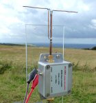
I set up the 1mW transmitter (garden shed) and powered it with an external 12V (ca. 300mA) power supply. My IC9700 was located in my ground floor radio room which was fairly constant in temperature.
I left both of these ON for an 1 hour before making the following measurements.
The Arduino that sends SPI data to the AD9850 frequency generator was set to 1296.1100 MHz but the frequency (at ca. 20 °C) was more like 1296.1075 MHz (assuming the IC9700 reads true).
Through the day the temperature in the shed ranged from about 22 °C (9 am in the shade) to 38 °C (3 pm in direct sunshine) and I was able to measure the change of frequency over this range.
In these simple measurements I simply tuned the IC9700 to 'zero beat' the CW signal (i.e. very low or no freq audio heterodyne) and read off the frequency at which this took place.
The slow code temperature values are generally a little higher (ca. 1 or 2 °C) than the shed temperature measured by the probe.
This may be because the electronics in the 1mW case (regulator IC etc.) produces its own heat and so the whole internals of the box tends to be a little hotter than outside.
There will also be a bit of a lag in responce between 'real' changes in the sheds internal temperature and what the 1mW temperature sensor reads in its box.
You can see the drift in frequency over the temperature range was never very great (the Tx never went out of band for example).
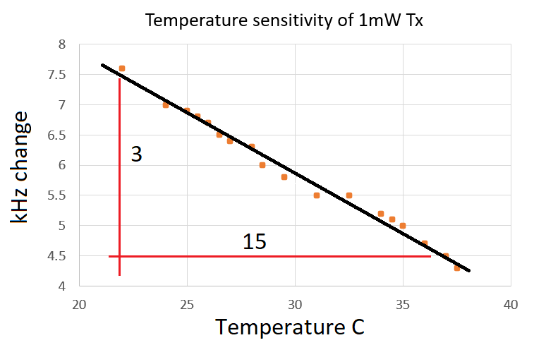
Roughly, the transmitter drifted by about 3.3 kHz over the 15.5 °C temperature change
giving a temperature coefficent of about = - 200 Hz / °C (± ca. 10 % or so)
As you can see there is a negative temperature coefficent i.e. as the temperature rises, the frequency drops.
If I wanted to undertake very low signal measurements on my 1mW signal over long distances (using phase sensitive detection techniques for example)
then I will need to provide better frequency accuracy and better frequency stability than I am currently getting.
A GPS reference for the AD9850, and for the timing of the slow code temperature data, would probably provide this.
| Time (UTC) | Freq. ν (MHz) |
slow code ±, 64, ... 1, ½ |
= °C | probe temp. = °C |
| 9:05 | 1296.1076 | 000101100 | 22.0 | 19.0 |
| 9:36 | 1296.1070 | 000110000 | 24.0 | 20.0 |
| 9:57 | 1296.1069 | 000110010 | 25.0 | 21.0 |
| 10:24 | 1296.1068 | 000110011 | 25.5 | 23.0 |
| 10:40 | 1296.1067 | 000110100 | 26.0 | 23.0 |
| 10:55 | 1296.1065 | 000110101 | 26.5 | 24.0 |
| 11:07 | 1296.1064 | 000110110 | 27.0 | 26.0 |
| 11:20 | 1296.1063 | 000111000 | 28.0 | 27.0 |
| 11:35 | 1296.1060 | 000111001 | 28.5 | 29.0 |
| 11:40 | 1296.1058 | 000111011 | 29.5 | 30.0 |
| 11:53 | 1296.1055 | 000111110 | 31.0 | 32.0 |
| 12:05 | 1296.1055 | 001000001 | 32.5 | 33.0 |
| 13:30 | 1296.1052 | 001000100 | 34.0 | 34.0 |
| 13:35 | 1296.1051 | 001000101 | 34.5 | 35.0 |
| 13:42 | 1296.1050 | 001000110 | 35.0 | 35.0 |
| 14:10 | 1296.1047 | 001001000 | 36.0 | 36.0 |
| 14:50 | 1296.1045 | 001001010 | 37.0 | 37.0 |
| 15:30 | 1296.1043 | 001001011 | 37.5 | 37.0 |
|

|

|
|
|

|
|
back to 1296 MHz page |
semi-rigid coax 3D printed mitre (bottom of page) |
3D printed templates for folded dipoles |
1mW 1296 MHz transmitter |
dipole with balun |
back to G1EXG radio page |
THE CREATIVE SCIENCE CENTRE
Dr Jonathan Hare, The University of Sussex
Brighton, East Sussex. BN1 9QJ
home | diary | whats on | CSC summary | latest news