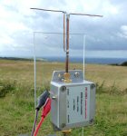
1296 MHz (23cm) band dipole
This is a very simple half-wave dipole antenna I made from 3.6 mm semi-rigid coax (RG402) and 1mm copper wire.
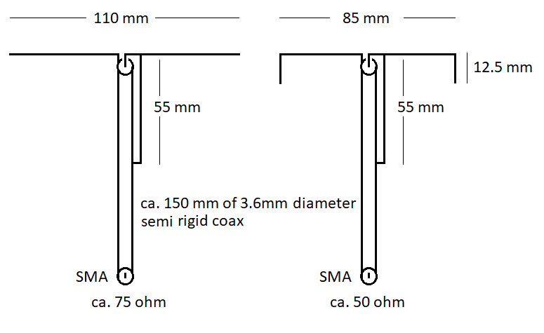
A ca. 110 mm length of 1mm diam wire was cut in half and soldered to the inner and the outer coax to form a dipole.
I added a quarter-wave balun (also made from 1mm solid copper wire):
one end was soldered to the coax inner while the other end was soldered onto the outer of the semi rigid coax,
further down from the dipole center (see diagram and images).
The wavelength is given by λ = 300 / ν
λ = wavelength (m), ν = frequency (MHz)
so for the 23 cm band the wavelength will be
λ = 300 / 1296 = 0.23 m = 23 cm = 230 mm
A half-wave will be ca. 115 mm
and a half wave dipole will tend to be slightly shorter than this, I chose ca. 110 mm
The quarter-wave balun will be ca. 110 / 2 = 55 mm.
The balun will be open circuit to 1296 MHz and short circuit to the second harmonic (2592 MHz).
The free space impedance of the dipole should be about 75 ohm.
By bending the ends of the dipole one can reduce the impedance closer to 50 ohm.
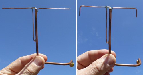
In my prototype I bent the last 12mm or so of each end as shown in the photos and diagrams
I don't know if this is really needed but it does make the small dipole fit into an even smaller space!
(if for example, you want to put all the apparatus into a water-proof box etc.)
|
|
|
|
|
|

|
|
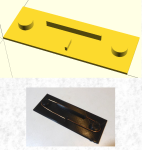
3D printed templates for folded dipoles |
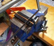
semi-rigid coax 3D printed mitre (bottom of page) |
back to 1296 MHz page |
1mW 1296 MHz transmitter |
DC5ZM UHF SWR meter |
temperature CW slow code |
back to G1EXG radio page |
THE CREATIVE SCIENCE CENTRE
Dr Jonathan Hare, The University of Sussex
Brighton, East Sussex. BN1 9QJ
home | diary | whats on | CSC summary | latest news