A low power 1296 MHz transmitter (ca. 1mW) / signal source
for outside / portable experiments
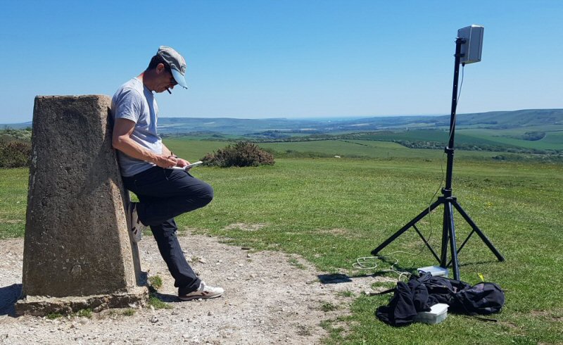
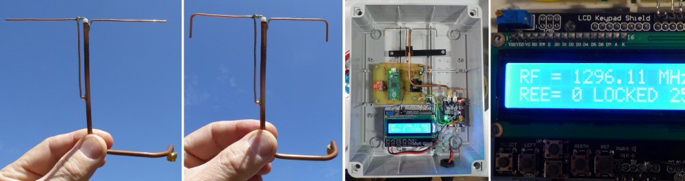
Left: Jonathan Hare nothing down some transmitter ON times. Right: the weather proof transmitter on a tripod
This page provides extra information to two articles I published in The RSGB Radio Communication magazine [1, 2] in 2022 about a low power (ca. 1mW) transmitter for 1296 MHz experiments.
PDF of 1mW Tx RadCom I article
PDF of 1mW Tx RadCom II article
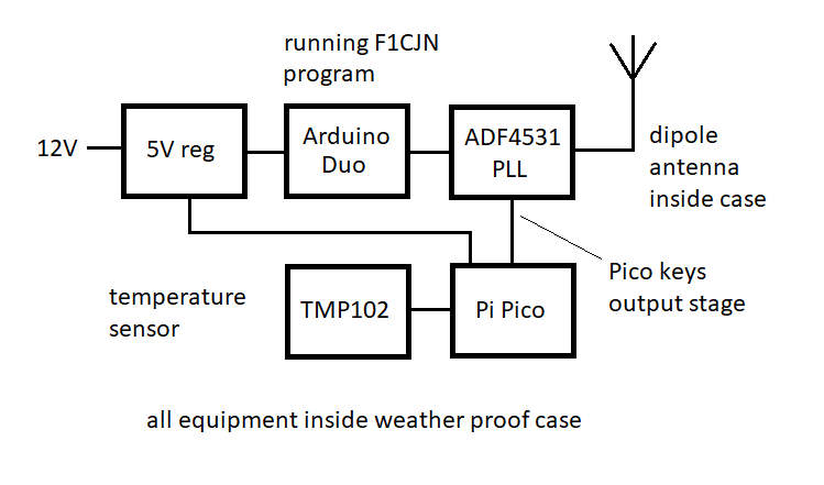
The transmitter consists of a ADF4351 PLL board driven by an Arduino Uno (with LCD display and input switches).
The output stage of the PLL board is also controlled ("keyed") by a Pi Pico microcontroller board.
Basic Layout
The transmitter block diagram is shown. In words; a 5V regulator powers the Arduino, LCD display, PLL board and Pi Pico. The PLL has its own on board 3V regulator but care is needed to ensure the clock, data pins receive 3V logic from the 5V Arduino. This is achieved using simple resistor potential divider circuits [3]. The PLL also sends back a 3V logic "in lock" signal to the Arduino, but this can drive the 5V logic of the Arduino directly [3].
The PLL needs a number of registers to be set before it will create RF. This is handled by the F1CJN code running in the Arduino. The code has memory storage of frequencies and memory 1 (M1) happens to be the frequency the unit will power up with. The LCD switch shield attached to the Arduino can be used to program this M1 start frequency. F1CJN web page has all the details, Note the English translation is just a little further down on his web page [3].
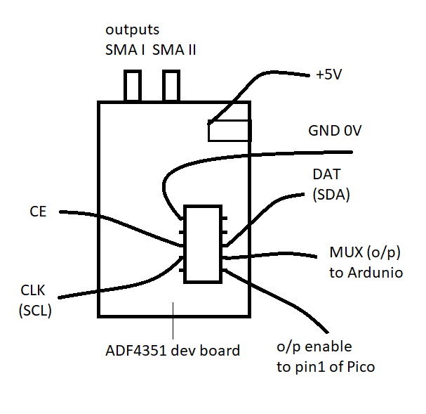
The PLL board has an output enable pin (normally pulled up - ON) that can be used to 'key' the o/p ON and OFF. In this prototype I have used a Pi Pico to key the PLL output.
Note: the Pi Pico uses 3V logic so is directly compatable with the ADF4351.
(Enable = 1 then RF output is on, Enable = 0 then output is off)
Note: add a pull-down resistor (1k - 4k7) from the Pi Pico Pin 1 to Ground (0V)
Pi Pico
My first 1mW prototype simply used a 555 astable timer to drop the RF carrier every 10 seconds or so for a fraction of a second (ca. 200ms). This meant the RF was on long enough for me to receive it properly and perhaps tune or peak an antenna setting, but off regularly enough to identify the signal as mine - rather than say from an internal receiver 'sprog' or some other unidentified received signal.
I soon realised it would be much more fun to use the carrier drop to send slow code data. I chose to send the internal case temperature using code run on a Pi Pico microcontroler reading a TMP102 temperature sensor IC. The temp data could for example, be used to determine the temperature dependant frequency drift etc.
Pi Pico pins:
Pi Pico o/p signal to drive PLL o/p stage CW ON / OFF = GP0 (pin 1) - add a 1k resistor to ground (0V)
TEMP102 sensor i2c: SCL on GP9 (pin 12) and SDA on GP8 (pin 11)
The Pi Pico is a really great and economical microcontroller development board that can be programed in C, Python or assembler. I chose to use Python for my code [4].
Note: The TMP102 temperature sensor is read / controlled using an I2C serial interface. I found the setup worked perfectly on a bread board but I needed to add a small capacitor (ca. 47 pf) between SDA and earth to get the sensor (Pi Pico) to function reliably on my printed circuit board. I am not sure why this is.
When I have time, I hope to use the Pi Pico to handle both the PLL register setting and the o/p keying so we won't need two microcontrollers (i.e. wont need the Arduino).
Python code
I am not an experienced Python programmer so the code is very basic; it could be written more elegantly (for example the Morse code sending routine at the start) ... but it works.
The code starts by sending my call sign in Morse (about 12 wpm). In the downloadable version of the code (on this page) I have removed my callsign and replaced it with G1GGGG. You will need to adjust the code for your call sign (there are some brief notes in the code on how to do this).
After the initial Morse code the program sends out a 'start bit' consisting of four ca. 300 ms pulses then goes on to send a 10 bit slow code that represents the temperature in two compliment. �One bit is sent every 10 seconds so it takes 100 seconds to send the complete 10 bit temperature value. More detail in the links below.
Details of the slow code were explained in the original articles [1] and in the links below.
A single 100 ms drop in the carrier represents a 0, while a double 100 ms pulse represent a 1. After the 'start bit' the most significant bit (±) is then sent, then the next bit (64 °C) until the least significant bit (1/2 °C) is sent last. The code then repeats these 10 slow code bits for as long as power is supplied [4].
Antenna
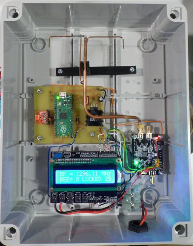
The 1mW transmitter is housed in a water proof case and in this version I fitted a 1296 MHz dipole antenna inside. Details of the dipole can be found in the links below [5].
Power output
It appears that F1CNJ has set the output to 1mW which I have confirmed using a DL6ZM micro-power meter [6].
The ADF4351 has two equivalent 50 ohm outputs one is 180 degree phase shifted to the other. I only used one of these outputs. In principle the other output (not used) should be terminated in a 50 ohm dummy load, but I have not found this necessary.
Feeding a two dipoles (one on each output), suitably spaced / positioned might allow a 3dB improvement.
It might also be possible to feed a full wave loop or quad directly from these two complimentary outputs. Presumably the combined outputs would have an 50 + 50 = 100 ohm output impedance which would suit direct connection to a full wave loop or quad.
Using the 1mW transmitter
Details of experiments using this transmitter can be found in part 1 of the RadCom articles [1]. Using the 1 mW transmitter out on the local hills my best distance so far has been ca. 9 km [1]. As the signal strength over the 9km path were quite strong (S6-7) much greater distances are obviously possible - provided we have a clear path between the transmitter and receiver.
MK I and later versions
These are the details of my MK I transmitter. As mentioned above I hope to use the Pi Pico to handle all the computing side of the project and this should allow a smaller and lower power unit to be created. Details of a MK II will be posted here [7] and on the links below.
References and links
[1] A 1mW transmitter for 1296 MHz (part 1), J P Hare, RadCom, July 2022
[2] A 1mW transmitter for 1296 MHz (part 2), J P Hare, RadCom, August 2022
[3] F1CJN 1296 MHz gen page
G4JNT PLL web pages
[4] 1mW Tx Python code
[5] 1296 MHz dipole
[6] Measuring power, return loss and SWR at GHz frequencies, DL6ZM, RadCom March 2020, p. 30-32.
[7] MK II link to add
THE CREATIVE SCIENCE CENTRE
Dr Jonathan Hare, The University of Sussex
Brighton, East Sussex. BN1 9QJ
home | diary | whats on | CSC summary | latest news