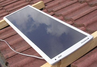
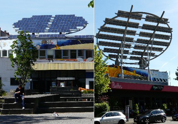
Solar cells
Jonathan Hare, The Creative Science Centre, Sussex University

solar panel


Please see the Vega YouTube science solar cell mini film
or for a better quality version see the original on the Vega Science Trust site

Introduction
Solar cells convert sunlight into electricity. Solar cells have been used for years on spaceships and satellites but now you see them on the roofs of houses as well as on electronic devices such as calculators, torches, radios and computers. Solar cells can be made very thin and flexible and have even been fabricated into clothes and tent materials for expeditions etc.

Conductors, semiconductors and insulators
Electrical properties are dependant on the ease at which electrons can flow through a material. When considering the electrical properties of solid materials there are three basic types: conductors (e.g. metals and graphite), semiconductors (e.g. silicon, germanium, cadmium sulphide) and insulators (e.g. plastics and diamond).

In solids the atoms are packed together closely often forming crystals. The bonding between the atoms is due to the outer electrons in each atom, these being shared or transfered between neighbours. If these outer electrons are tightly bound to the atoms they will not be free to travel through the material. Materials like these can not conduct electricity well and are called insulators. In materials such as metals some of the electrons are completely free to move throughout the material and so the conductivity is very good. Semiconductors are materials where the bulk of these 'conduction' electrons can only be freed by heating or by providing some form of external energy such as light etc.

photo cell with light photo cell without much light
A photo cell is shown at the bottom of the photo. You can see that when it is in the light the conductivity meter shows a greater reading (less resistance) than when I cover the photo cell with my finger (to block out the light)


Photo cells
A photo cell can be made by connecting wires to a small piece of semiconductor material (e.g. cadmium sulphide, CdS). CdS responds well to the energy of sunlight and its resistance varies with the intensity of light falling on it. A typical CdS cell may have a dark resistance of 1 million ohms while dropping to only a few 100's ohms in sunlight. Because the resistance of the photo cell changes when light shines on it these devices are often called a light dependent resistor (LDR).

lamp
The device on top of the street light is the light (dark) activated switch containing a photo cell


It is important to realise that the photo cell is not generating electricity from the light, rather the light just changes the electrical conductivity. Photo cells are useful for light meters and light switches. Street lights often have a photo cell light switch on top of the main lamp which is designed to turn the light OFF in the day and turn it ON at night.

Solar cells - the PN junction
In order to make electricity from sun light we need a more sophisticated semiconductor device than a simple photo cell. What follows is a very simplistic explanation of how a solar cell works.

Semiconductors can be doped to change the properties of the material. 'Doped' means that the pure semiconducting material is chemically modified with small amounts of a specially chosen chemical to enhance some aspect of its physical properties. Semiconductors doped with a chemical that will increase the quantity of free electrons (negatively charged particles) are called N type semiconductors. Semiconductors doped with a chemical that will increase the quantity of holes, the absence of electrons (which flow in the material as if it were a positive charge) are called P type semiconductors.

PN junction


If you could bring together thin discs of P and N type semiconductors (like two coins stacked on top of each other) something interesting takes place at the junction between the two surfaces. Holes move from the P type material into the junction, while electrons will come in from the N type. Electrons and holes keep arriving till the total charge they bring with them creates a voltage that eventually stops the process continuing further. The two discs now form a complete semiconductor device called a PN junction. By connecting wires to the ends of the P and the N type materials we can create a very useful electronic device (Note: in practice a PN junction is not actually made this way but will be fabricated in one whole process).

In the junction when an 'electron' meets a 'hole' it results in a thin insulating region which has this built-in voltage present across it (see above). This internal voltage is not assessable from outside but it does effect the properties of the device. The result is that if a voltage is applied to the device we find that current only flows in one direction - the PN junction is what we call a diode. (btw there are devices called PIN diodes where the insulating region is relatively large and so have low capacitance).

Most PN junctions will be sensitive to light and so diodes and transistors are usually fitted into dark plastic or metal packages. If you carefully cut the top off a metal transistor and connect a meter to two of the connections you can use the tiny transistor to make electricity from light! Unfortunatly the area is less than 1mm x 1mm and so it does not produce much power. I used the effect in an experiment I made for the Death Valley Rough Science TV series when I needed a light detector device for a light communication challenge.

Infrared (IR), visible and UV light
Solar cells will produce electrical energy not only from the visible light we can see but also from Infrared (IR) and ultraviolet light (UV). As most of the light from the Sun is in the visible the peak electrical energy will probably be from the visible part but UV can play an important role in solar cell electrical generation. Plastic absorbs UV so if a solar panel has a transparent plastic protective window it will block the UV getting to the cells. In some cases this may actually prolong the life of the cells as UV can cause damage.

How does sunlight liberate electrons?
Most electrons in a material are locked into place in chemical bonds, as I described above. However a single particle of light (a photon) is a packet of energy, and that energy can be absorbed by the material and then used to kick the electron out of its chemical bond. Some materials are better adapted at this than others. For example low energy sunlight (red light, and infra-red light) may not have enough energy to kick electrons out of their bonds. So different materials may absorb sunlight in different regions of the spectrum, but it is difficult to find a material that releases electrons for photons arriving with all the different energies of the spectrum. This can limit the efficiency of a solar cell.

For example diamond, that is transparent to all light from the infra-red to the ultra-violet, would make a rubbish solar panel! New materials science research, and particularly nanotechnology research, is working towards designing new materials that can more efficiently trap the incoming sunlight, over the widest range of the spectrum possible. Materials such as silicon are pretty effective at their job but are very expensive to make clean of defects, and newer materials such as CuInGaSe can work better but contain expensive and rare metals. Researchers are trying to develop new materials made from carbon such as fullerenes that can efficiently release electrons after absorbing sunlight, since these in principle could be cheaper, more environmentally friendly, and with the added advantage of being flexible like plastics. So in the future it may be possible to roll up and fold solar cells made from organic materials such as these.

Going back to the PN junction if the solar cell device is made quite thin sunlight will be able to pass into the junction and liberate electrons. The electrons are swept away by the internal field in one direction and a voltage appears at the electrodes as a result. If you connect a circuit to the two connections a current can flow. Unlike the photo cell, which just produced a change in resistance when light falls on it, a PN junction light can convert light into electrical power.

A single solar cell creates about 0.6V. The current will depend on the intensity of light falling on the device, the surface area of the cell, the reflectivity of the device etc. Typically a small cell ca. 5cm x 5cm might generate 0.6V at 100mA in full sunshine.

Note: Solar cell efficiency varies with temperature and so the hotest place may not always the best place to generate electricity using solar cells, even though there may be very good quality sunlight.

radio gear


Charging a 12V battery
As each solar cell produces about 0.6V so in order to charge a 12V battery we will need ca. 12 / 0.6 = 20 cells. In practice we tend to wire up a few more to create say 14V so we always have a bit extra to be able to charge a battery properly. Modern solar panels may look like one single cell but are actually composed of a number of cells joined seamlessly together (see photo at top of the page).

solar panel


Protection diodes
In the day, when there is plenty of sunshine, we can use the solar panel to charge up a battery. At night we need to make sure that the battery does not discharge itself through the panel.
In principle the solar cells are diodes and so should not conduct in reverse (at night) but there will always be a slight leakage which will mean the battery will lose power. You can solve this problem simply by using a standard diode (which has much better reverse characteristics than a solar cell 'diode') between the solar cell and battery. Unfortunatly you lose about 0.6V when you use a diode, which is one reason why the panels are designed to make a little more than 12V (e.g. 14V).

solar regulator


Regulators
A better way of handling the power generated by the solar panel is to use a regulator unit. This has two functions. Firstly it regulates the voltage from the solar cell so that even if the panel produces say 16V the unit will pass 12V. Secondly it continually adjusts the power going to the battery to stop over-loading or over-charging. It does this by letting 100% of the 12V power through when the battery is uncharged but then as the battery starts to get near to fully charged it reduces the power by pulsing the current ON and OFF. As the battery becomes charged the ON pulses become briefer and briefer.

radio gear


Typical Applications
You can see the solar cell panel I use in the photo at the top of the page. It produces 12 to 14V at 12 Watt in good sunshine. I constantly use my panel for two applications. Firstly I use it to charge a 12V battery that runs my amateur radio (shortwave) equipment. I am a license radio amateur and talk to people all over the world using my solar powered equipment. My other application is that I use the solar cell to charge two batteries that are part of an emergency desk light. This gives me roughly four hours of light in case of a power cut etc.

two solar cells


Solar cell positioning
In an ideal world, to get the maximum power from our solar panel we would want to continuously track the Sun. In other words follow the sun in the morning as the rotation of the earth makes it appear to rises in the East, move to its zenith at midday and then set in the west. Large solar cell installations can actually use some of the solar power to drive computer controlled motors and servos to do just this. Most of us haven't the space or the money to have such an advanced set-up and have to do with a relatively small panel fixed somewhere on our roof.

So what is best, a west, east, north or south facing roof? I took two solar cells, wired them to resistors (as simple loads) and logged the voltage developed by the sun. I positioned these two panels slopping at 45 degrees and logged the voltage they produced. In the first measurements I pointed the pair east and west and then the next day I tried them north and south. In both cases the cells were fixed on top of a 6m mast well above the surrounding objects to limit shadows and obstructions.

Note 1 - this is a simplistic analysis and is given only as a rough guide.
Note 2 - To get an idea of the power developed in the resistor I should square the voltage and divide by the resistance (P = V² / R). I haven't done this here as we are only using the data to make simple comparisons. But bear in mind that any conclusions we make based on these voltages will probably apply to an even greater extent when we consider the power.

Simple analysis
All the graphs start at 4am and end at 10pm (BST) and were recorded in May 2011 in southern UK. The recording days were sunny but with patchy clouds. All the plots show voltage spikes and these are due to the odd cloud covering the sunlight every so often. Not surprisingly we can see that the east facing set-up shows the greatest voltage during the morning while the west facing panel showed the most voltage during the last half of the 'day'.


east facing data

East facing solar cell - showing most voltage in the morning.


west facing data

West facing solar cell - showing most voltage in the evening.


The north facing panel is the most surprising. It shows the most stable and most continuous voltage profile (but not the greatest power). At this latitude the sun rises and sets quite north of due east and due west and so the north facing panel actually gets direct sunlight at these times. The other arrangements are always in shadow at some part of the day. The result is that the north facing panel produced the longest continious period of voltage of any arrangement. It is however on the whole the lowest voltage. As the power is dependant on the voltage squared this is therefore not the best arrangement. However if you had a low power application that needed continious power throughout the whole 'day' (such as perhaps a solar powered parking meter for example) then a north facing panel might be quite satisfactory.

north facing data

North facing solar cell - low voltage but for longest time.


south facing data

South facing solar cell - greatest voltage but during the middle of the day


The south facing panel shows the greatest voltage produced as it was the only panel that was pointing at the sun at its most brightest (highest) point at midday. If we consider that the power is proportional to this voltage squared then we can see that the south facing panel actually produces the most power of the lot. However it actually produces the shortest period of voltage of the four arrangements. This is because the panel is actually in its own shadow for some of the morning and some of the evening (as the sun rises and sets quite north at UK latitudes in May).

Overall then, ignoring the peculiarities of the weather etc. (i.e. if we assume we are talking about a blue skies clear day) to get the most power from your solar panel its probably best to have a south facing roof. But as you can see an east or west facing roof will still provide some useful power over some part of the day.

building in Hannover, Germany
A solar powered community center in Hannover, Germany.


Acknowledgements
Jonathan would like to thank the COST and NanoTP projects as well as Gill Watson and Richard Inskip (The Vega Science Trust), Bernd Eggen and Chris Ewels for inspiration, discussion and helpful comments. This article is intended to provided more information for those viewing the Vega Trust mini film on 'solar cells' (see links at top of the page).

funding logo II funding logo I


References and related links
[1] Solar Energy, Understanding Global Issues, 1996. ISBN 0 85048 963 6
[2] wiki solar cell page
[3] parbolic solar heater
[4] Solar pool heater


THE CREATIVE SCIENCE CENTRE


Dr Jonathan Hare University of Sussex, Brighton.
e-mail: j.p.hare@sussex.ac.uk

home | diary | whats on | CSC summary | latest news