Rotary encoders and the BBC Micro:bit
The rotary encoder
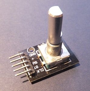
The rotary encoder I am using is pretty standard and I got them on e-bay (search for "KY040 Rotary Encoder")
The device has four main connections: +V, 0V, o/p A and o/p B. There is also often a fifth connection which is a switch fitted to the shaft activated by pressing the knob (rather than turning it).
The later feature might be used to select a 'course' or 'fine' action when the knob is rotated for example.
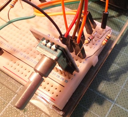
Note:the rotary encoder may have different markings, the one I used was marked (see photo above):
GND which is 0V
+ which is +V
CLK which is o/p A (or o/p B)
DT which is o/p B (or o/p A)
SW which is the push switch
Note: o/p A is identical in function (but not action) to o/p B. So in the following experiments if the program behaves in the reverse way to that expected, then you can simply swap the A and B connections.
How the rotary encoder works
As you turn the knob you feel it click through each position on its way around. There is no 'stop' so you can turn it either way continuously. There are two o/ps from the encoder: A and B. In the rest positions between the clicks, or steps, the A and B are either both on or both off. As you turn the encoder, the way A and B change state relative to each other depends on the direction the shaft is rotating (i.e. clockwise or anti clockwise). You can therefore determine the rotation direction in the software by making use of this 'phase' difference between A and B as they change.
How it works diagram
The diagram helps to show how the rotary encoder works, from one 'click' to the next.
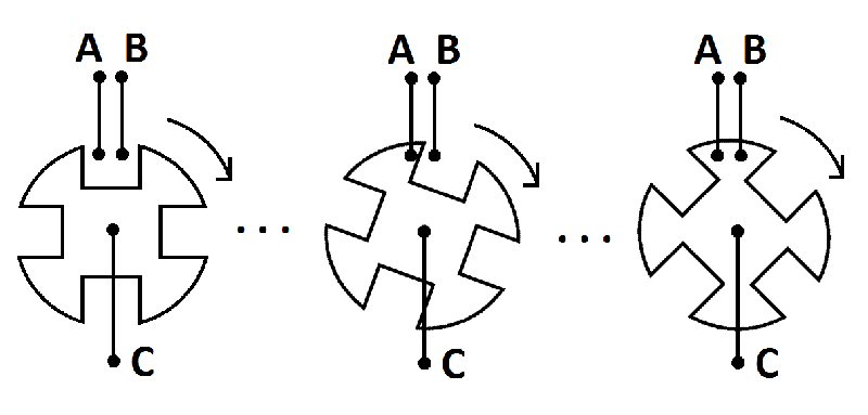
In the left hand picture (before the shaft is rotated) you can see in this example that A and B are initially not connected by the moving part of the switch (which is connected to the rotating shaft, C) and so the pull-up resistors (not shown) will make A and B 'high', or 'on'.
As the shaft turns and the switch moves across, you can see that by the second picture it has made contact with A (turning it off) but hasn't yet got to B so this will still be pulled 'high'.
By the third picture (one 'click' on from the first picture) both A and B are now connected and are thus both low. The middle diagram shows the intermediate position, between 'clicks' where we measure the phase of A and B to determine the rotation direction. You can see that if the shaft was turned the other way (anticlockwise instead of clockwise) the moving part of the switch would cause A and B to change in the reverse order. The software can check the way A and B vary relative to each other so that it can determine the direction of the rotation of the shaft.
If you wire the A and B switch connections to two LEDs (each with series current limiting resistors), so say A=red and B=green (take the common of the LEDs to the positive supply). We can see how the rotary encoder works by the way the two LEDs flash on and off. For example both may initially be OFF, then when you start to turn the encoder clock wise the red LED will come on. Then a small rotation later both the green and red light will be on and by one click later they stay ON. Turning through another clockwise click the red will go off followed by the green and then both are off when the switch clicks again. For an anticlockwise rotation the LEDs turn on and off in the reverse manor.
So the clockwise LED lights go:
both off
red on, green off
red and green on
red off, green on
both off etc ...
So the anti-clockwise LED lights go:
both off
green on, red off
red and green on
green off red on
both off etc ...
Phase between A and B
If you plotted out the way A changed as you turned the encoder continuously in one direction you would see a square wave of pulses going on and off. If we plot B at the same time we would see exactly the same series of pulses except that they would be shifted slightly. The A and B pulses are actually 90 degrees out of phase with each other. This phase difference provides the information needed to determine the rotation direction - clockwise or anti clockwise.
Grey code and exclusive OR
If you want to know more about the pulse phase relationship, grey codes and how to use an exclusive OR gate to determine the rotation direction, there is a very interesting article in the reference section below
[3].
The code
We want to use the pulses from the rotary encoder to make something interesting happen in the software, it might be to change the pitch of a note, or change the position of an object in a game for example. To do this in the code you will probably want to make a counter / verable go up and down in value as we change the position of the knob on the rotary encoder. We will then use this value to control something in the software (which is what my rotary encoder BBC Micro:bit software example does below).
Watching what the encoder does
The program must monitor A and B constantly if important information is not to be lost. Obviously this only needs to be done in the part of the program dealing with these settings, but you have to be careful with the program structure otherwise the program might be doing something else when it should be monitoring the encoder and miss you trying to tell it you want to do something! If it was the volume, or pitch on an electronic musical instrument this might be irritating but if it was the steering control of a wheelchair or car it could be very important.
Has anything changed?
The first step is to see if the knob has actually been turned. The easiest way is to read A and store its value, then quickly read it again and see if it has changed. If its not different the knob has either not been turned or you have been unlucky enough to read the encoder just at precisely the same time it took to do two (or an even number) of clicks of the knob and it just happen to be in an equivalent position! This is unlikely, but could happen. You can mitigate against this by making sure you scan A and B very fast - which is usually the case in a fast circuit like a microcontroller on the Micro:bit (but as I just wrote, take note that you need to check the computer is not spending valuable time doing another job when it really should be reading the rotary encoder).
In words we need to check:
If A does not equal the last value of A - then the shaft must be rotating.
If A does equal the last value of A - then shaft is not rotating.
Interupts
There is a way to force the computer to take notice of what the encoder is doing even if the computer is away running another part of the program - using a thing called interrupts (interrupts because they interrupt what the computer is doing to pay attention to something you regard as a higher priority). We are not going to look into interrupts here but it is an interesting and important part of programming.
Determining the direction of rotation
If A has changed then we now know the shaft has been turned but we can't yet tell which way (clockwise or anticlockwise). To do this we need to quickly measure what B is doing. It's transitory state (or value) will be determined by what state it was last in and if the encoder shaft is being turned clockwise or anti clockwise (e.g. see diagrams above).
Which direction?
Once you know the shaft has been rotated (by monitoring A for change) we now need to see what B is doing.
Note: this is a changing / transient value and so is harder to detect (i.e. easier to miss) than the first test on A. We are seeing how its value changes quickly during the motion of the switch - as it goes from one 'click' to another 'click' (see middle picture of the diagram).
If we are sure that the shaft has moved (by checking A) then if we now test B and find it is the same as A was (before it changed) we can take 1 away (decrement) from a counter. If B has changed then add 1 (increment) to the counter.
There are only two directions the shaft can take, so if you can't work out which direction it happens to be from the diagram, don't worry when you try it out, if it goes the wrong way simply swap the port numbers in the software, or swap the physical connections to the encoder.
So finally the rotation detection code comes down to this:
If A has changed from the last value then read B
if B different from last value of A add 1 to the counter
otherwise subtract 1 from the counter.
BBC Micro:bit - setting-up & problems
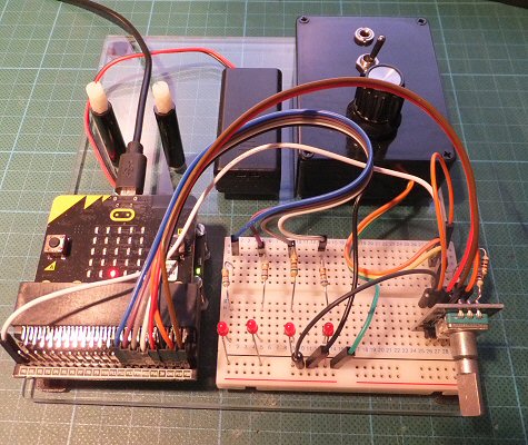
In the most basic set-up for this test program I have only used two inputs on the BBC Micro:bit: port 19 and port 20 (for the two rotary encoder A & B inputs). There are also connections to ground (0V) and the 3V supply on the Micro:bit. I used the built-in LED display on the micro:bit. In the photo you can also see four LEDs wired up on the bread-board but these are for other experiments. At first I could not get the Micro:bit to detect the encoder pulses at all - the circuit would not work. The encoder has built-in 10k ohm pull-up resistors (resistors wired to the positive supply) and these were a bit too high in value to work with the Micro:bit input circuitry. Adding 1k resistors across the built-in resistors solved this issue. This can be done on the pins of the encoder, at the Micro:bit or on a breadboard if you are using one (see photo). You may be able to get away without adding 1k resistors if you make use of the Microbit 'switch test' function (see ref. 2 at the end of this page). I havent done this here as its useful to work around the problem here so you dont get into trouble with future projects. To save power it might be worthwhile trying slightly higher resistance values (say 4K7 first try) to see how large a value will work (even extra 10k will reduce the total in circuit to 5k).
Some example test programs / code
So far I have made up three simple test programs (see links below), the first two use ports 19 and 20 to detect the rotary encoder direction the third also uses the push-switch on the encoder on port 16 (to get this to work you push the knob down rather than turn it). The first lights one of the 16 LEDs that are around the circumference of the 5 x 5 LED Micro:bit screen. We start off in the middle (position 8 on the counter) at the bottom. Turning the encoder clockwise will make the dot move clockwise (counter -1) around the circumference and turning the encoder anti-clockwise will make the dot move the other way (counter +1). If the counter goes to zero we make sure the software does not allow it to go below zero. If the counter goes to 16 we make sure it does not go above 16. This way we keep the number of possible steps within the boundary of the 16 LEDs we have got on the Micro:bit display. You would of course not want to be restricted this way for other applications.
The second simply runs through 0 - 9 on the LED display as you turn the knob. If you go over 9 (or under 0) it just stays at that value.
The third program is the same as the second; it counts from 0 to 9 but I have also added in a test to see if you have pressed the encoder, if so the code resets the screen to 5.
Hopefully you can use these examples to build your own exciting code :-)
Note o/p A is identical in function (but not action) to o/p B. So in the following experiments if the program behaves in the reverse way to that expected, then you can simply swap the A and B connections.
Final extra bits (!)
I mentioned that you need to make sure you read A and B regularly to get a stable response from the encoder. I came across an entry on a forum (see ref [1] at the end of this page) saying that an extra AND statement was needed to get the encoder to work properly. There was not any feedback on the forum, so I have explore this here: Although the outputs from A and B are square wave and symmetrical, when we look at the difference between them the result can sometimes be very short or rather long because of the phase difference. For example in the switch diagram the B pulse only goes low towards the end of the 'click' while relatively A is on almost to the end of the 'click'. We can include an extra AND statement to ignore half of the pulses to ask less of the computer, to try and stabilise the response. I found this mod did work but because you are ignoring half the pulses you need to turn the knob two clicks, instead of one to get a response!
If A has changed from last value of A AND A =1
then read B
if B different from last value of A add 1 to the counter
otherwise subtract 1 to the counter.
|
rotary encoder and 16 LEDs |
rotary encoder 0-9 counter |
rotary encoder 0-9 counter & push-set to 5 |
more soon | more soon |
|
[1] rotary encoder |
[2] BBC Micro:bit encoder ref |
[3] Grey Code PDF | more soon | more soon |
back to my BBC micro:bit page |
THE CREATIVE SCIENCE CENTRE
home | diary | whats on | CSC summary | latest news