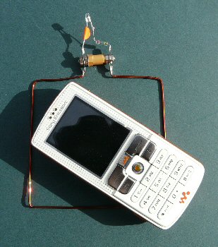
Fig. 1: left: mobile phone radio wave detector and right: the simple schematic
IMPORTANT NOTE: this device works very well on the old style mobile phones (as shown in the photo above). However, it does not always work well with modern smart phones. This may be because modern phones use higher frequencies, less power and use the power in a slightly different way (e.g. spread spectrum). Some smart phones do work and success may be due to the signal strength of the local mobile phone mast nearby. If you are in a low signal area the phone will create more power to ensure reliable communications. If you are in a very strong signal area (very near the local network) your phone will drop its output power and consiquently there will be less power to pick-up and to convert to a voltage to light the LED.
Described is a simple low cost home-made device that converts the radio wave energy from a mobile phone signal into electricity to light an LED. No battery or complex circuitry is required. The device can form the basis of a range of interesting experiments on the physics and technology of our mobile phones.
EM radiation and radio waves
Mobiles make use of various bands of radio frequencies to communicate between the mobile to base and the base to mobile: in Europe these include 900 and 1800 MHz (850 and 1900 MHz in the USA and Canada) [2, 3].
The relationship between wavelength, speed of light and the frequency follows the well known formula:
Wavelength λ (m) = speed / frequency = c (ms-1) / ν (Hz)
λ (m) = 300,000,000 / ν (Hz) or approximately:
λ (m) = 300 / ν (MHz) ..... Equation 1.
So for a mid-range of about 1000 MHz (1 GHz) we get a typical mobile phone wavelength of about:
λ = 300/ 1000 = 0.3 m = 30 cm.
Simple radio wave detector
The loop consists of about a wavelength of wire, ca. 30 cm so each side is about 30/4 = 7.5 cm. The dimensions are not critical. The two ends are connected directly to a simple series circuit consisting of a high brightness LED and a germanium diode. They need to be connected correctly. All these components are cheap and readily available from electronic stores [4].
The loop can be made from a piece of copper wire roughly bent into a square (although a circular loop or rectangle will also work). If the wire is insulated remember to scrap off the insulation and solder-tin the ends. Simply solder the germanium diode and LED into circuit as shown in the diagram.
On a new LED the long lead is the positive (anode) while the short lead is the negative (cathode). The germanium diode has a line (band) around the end which is the cathode. When correctly wired the LED and the germanium diodes are connected so they both allow current to pass in the same direction, i.e. in the circuit diagram the arrows point in the same direction. In practice this means the LED and germanium diode are joined at the cathode of one and the anode of the other.
In my prototypes I used an insulator between the loop ends (light coloured cylinder in the photo) to make the whole thing more sturdy but this was purely for mechanical reasons and is not needed for the circuit to function properly. Note: a much more sensitive version using a x10 and x100 DC amplifier is described on my web site [6].
How it works and how to use it
When a radio wave passes across a metal object the EM fields cause the charged electrons in the metal to oscillate and this causes small AC currents at the same frequency to be induced into the metal. If a mobile is brought near to the loop and a call or text is made [5] the radio waves emitted from the phone pass across the loop. This induces a voltage into the antenna (the loop) and if it is close enough will be large enough to light the LED. As the loop is about one wavelength in size it is resonant and so there is a good transfer of power (low reactance) between the radio wave and LED.
The mobile phone automatically tests the network and adjusts its transmission power to maximise the battery life and minimise network interference. As a result the brightness of the LED will depend on the data being sent (the average signal), the local signal strength and how close the loop is to the phone.
Why the second diode? - It's curious why the germanium diode is needed at all. The LED is a Light Emitting Diode after all and one would not think that another diode would help. However
my initial experiments failed because I had not included it. The LED will have a relatively high capacitance which at these frequencies will tend to de-tune the loop and short out the LED. The germanium diode however is made up of a tiny wire which only makes a point-of-contact onto a piece of semiconducting germanium so it's 'self' capacitance is very low keeping the loop resonant.
The germanium diode will rectify the AC signal from the loop forming a series of DC pulses that will be nicely smoothed by the LED's capacitance. Without the diode however the raw AC signal from the loop will tend to be averaged to zero by the LED's capacitance.
Other size loops
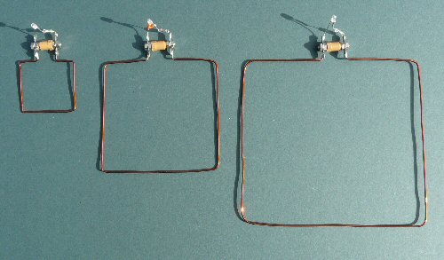
Fig. 2 shows a set of three loop devices with edge lengths of roughly 3.7, 7.5 and 15 cm. You can find out for yourself that the best match to the mobile signal is with the full wave loop of ca. 7.5cm per side. The other loops do work to varying degrees however (smaller ones may work better for the 3G network). The larger loop works well for the '70 cm' amateur radio bands.
Polarisation
The electric and magnetic fields making up the EM wave are orthogonal (they are at right angles to each other as they pass through space) to each other but depending how they are generated by the transmitting antenna can arrange themselves in any orientation with respect to the ground. If the electric field is parallel with the ground we say the wave is 'horizontally polarised' while if its normal to the ground we say its 'vertically polarised'. The loop antenna will respond best to one type of polarisation (depending on its orientation) so it's worth experimenting with the orientation of the mobile (or the loop) to get the strongest signal - brightest LED.
Mobile antenna
Inside your mobile phone is a transmitter / receiver and antenna. Many mobiles have this antenna at the top of the phone but some of the PDA type phones have it at the bottom. As a result you can locate the position of the antenna by moving it around the center of the loop till you get maximum LED brightness.
Networks
There are various different networks that a mobile may use both in the UK and abroad. It may be that you need to adjust the network phone settings on your mobile i.e. change from "automatic select" to set for "GSM" so as it get the strongest signal to light the LED. Note: the 3G network might not be powerful enough to light the LED. As the GMS network is currently the main network over the UK the device should work anywhere where you can get a signal as long as you check the correct selection on your mobile menus [5, 7]. The 3G network operates on a higher frequency (smaller wavelength) so you might find a smaller loop will work better than the main one described here. See 'other experiments' section below.
Test signals
In order to pick up the radio wave energy from the phone it obviously needs to be transmitting a signal. There are a few ways to do this:
1) On switch 'on' (or change of network) you can see that the mobile initially transmits for a few seconds to the network to tell it it's there (especially if you have moved since turning it off). You don't actually need to dial a number to detect these signals.
2) Even if don't text or call, throughout the day the mobile will send out data to 'keep up' with the network, especially if you are moving around (going through train tunnels etc. see below).
3) When you make a phone call you will transmit. Initially there is quite a lot of data being sent but in a few seconds data / power only gets transmitted when you speak. So to light the LED continuously you need to talk or provide some background sound continuously. Your service provider voicemail might be a good free phone number to try for these experiments [5].
4) Texting is the easiest way to show the radio wave power being transmitted. Long texts will light the LED for longer than short texts.
5) Finally set up the mobile on the loop and use another phone to text or phone the mobile. Even though you are not directly using the phone you will see that even on 'receive' the mobile phone transmits data to and fro. Ring off before you get charged.
Note: If you can use a free phone number it will save you money [5].
Other experiments:
Hearing data - if headphones are wired across the LED they will convert the voltages into sound and you can 'hear' the clicks of the digital data being transmitted. These are the same clicks that so easily get picked up by sensitive electronics such as a stereo amp or recording equipment when making a video for example. Hence - 'no phones on' when filming.
Logging data - if a meter, or better still a stand-alone data logger, is attached across the LED then one can monitor the EMR from the phone. For example even if you are not making a call your mobile will send signals too (and receive signals from) the network while travelling around. Fig. 3 shows a simple modification using a de-coupling capacitor so that a coax cable (or twisted pair) can be used to go to headphones, meter or data logger. Note the diode has been reversed so that the logger has the correct + and � connections for a unipolar input logger. The capacitor should help average the signal and stop radio frequencies going down to the logger. If one is available a few turns of the wire can be wound within a ferrite ring near to the logger so that maximum immunity to the mobile phone signal can be obtained for the logger electronics.
Out and about - Once you can log data you can discover all sorts of interesting things your mobile phone is doing without you realising it. Fig. 4 shows the plot over a few hours of travelling between Brighton and London (and within London) on the train. The detector was simply placed near to a phone that was not making or receiving a phone call or text, but was turned on.
The graph shows that the mobile sends out signals to tell the network where it is as it travels along and in particular goes in and out of long train tunnels. The peak heights vary because of the different powers the mobile transmits at depending on the signal strength of the local network and also because of the way the data logger 'snatches' a reading from the circuit every few seconds. As your phone sends out data onto the network to ensure the very best communications as you move around, so your mobile and the network obviously knows where you are and where you have been. Thieves and criminals beware the police can track you!
The inverse square law - If the transmitting mobile phone is moved away from the loop one would expect the signal to drop off. Unfortunately because both diodes need a certain threshold before they conduct the detector is not sensitive to small signals and not very linear. Therefore it's not very easy to use the device to measure the inverse square law (drop in signal v distance away) but of course you can see the signal go down. You could perhaps use the device to plot isobars - i.e. plot the equal intensity signals around the phone / nearby objects.
Changing the resonant frequency of the loop - you might be able to make some simple sliding mechanism (e.g. a small trombone-like mechanism) out of metal tube for example to tune the loop device for different frequencies. Then you can use it to find the average wavelength and so determine the center frequency by adjusting the size for maximum brightness of the LED. The wavelength can be determined by measuring the total distance around the loop. If we assume the antenna is one wavelength in total length then the frequency can be established by rearranging Equation 1, i.e. ν (MHz) = 30,000 / L (cm), where L is the length around the loop (cm).
Note: You will need to allow the transmitted digital signal to 'settle down' i.e. make measurements only after a few seconds after dialling / pick up so that only the sound data is being transmitted rather than the initial connection data. A constant sound will also need to be made so that the mobile phone continuously transmits data. It's worth playing music near to the phone or constantly whistling to keep sound coming into the phones microphone.
Mobile phone detector - teachers who want to know if the students / pupils really have turned-off their mobile phones (rather than just put on 'silent') can wire the loop device into the class room white-board speakers. Any mobile that is on in the class will send out signals which (if you are close enough) you will hear the data going to and fro - you will have your very own 'who's got their mobiles on' device which might be useful for exams etc.
Summary
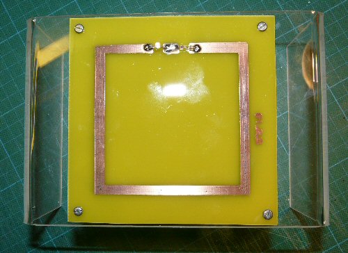
All in all then, for such a simple easy to make device I hope you agree that there is a lot of scope for interesting science / technology investigations with your mobile phone. The device would make a good science week project (for radio amateur clubs etc.) A 'deluxe' pcb version (Fig. 5) on a perspex display case (Fig. 5) is currently going around the southern UK as part of the SEPnet outreach work, see the 'Radiation Exhibition' [8] and also as part of my on-going lecture series [9].
Post publication additions
(What follows was not included in the published article as this calculation was worked out later). A full wave loop is resonant and so looks purely resistive to the radio waves. Such a loop will have a resistance of about 100 ohms (Note: this is the AC resistance and not the DC resistance which will be very low). Now power P = V x I (V = voltage and I = current) and resistance = R = V/ I therefore P = V2 / R or rearranging V = √(P x R) which means that the voltage created by a power level of say 50mW (say for argument that roughly half the mobile phone power) arriving at the antenna will be about V = √(100 x .05) which is aprox. V = 2V, enough to light an LED.
References
[1] These ultra high frequencies (UHF, > 1000 MHz) are also often called microwaves.
[2] wiki pages
[3] Elektor Electronics magazine, June 2005
[4] order codes for the germanium diode and LED are:
e.g. Germanium diode: Maplin Electronics: QH71N, Rapid Electronics: 47-3114
e.g. LED: Maplin Electronics: UF72P , Rapid Electronics: 55-0085
[5] to save money use your voice mail service (often you simply dial 121).
[6] for details of an amplified detector see: wavemeter
[7] select 'network setting' from the mobile phone 'settings' menu and then go to 'network mode' and select 'GSM 900/1800' rather than 'automatic'.
[8] SEPnet mobile phone device on display throughout southern UK.
[9] for details of my talks see: talks and workshops
THE CREATIVE SCIENCE CENTRE
home | diary | whats on | CSC summary | latest news