MOBILE PHONE ABSORPTION WAVEMETER
Note: for details of talks and workshops on this topic click here:
talks and workshops
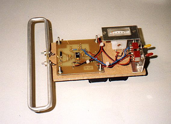
Description
An absorption wavemeter is a device which can make measurements on the
strength of radio
emissions and so this instrument is an essential item for investigating the
mobile phones.
In principle an absorption meter is a simple device that can be constructed
from an antenna,
diode (a simple electronic component) and a meter. This simple circuit
lacks sensitivity
though and so measurements can only be made very close to the transmitter.
The circuit
described below incorporates an amplifier whose gain can be set by just one
resistor.
Gains of say x 10 can easily be obtained thereby greatly improving the
usefulness of the
meter.
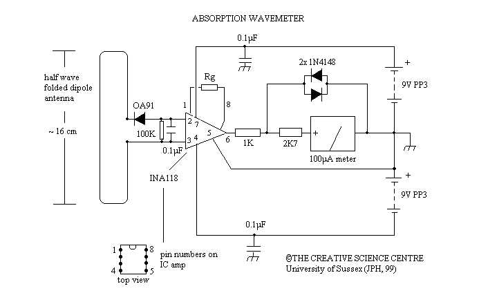
How it works
Small radio frequency voltages are induced into the wavemeter antenna when
an active
transmitter (mobile phone) is nearby. This voltage is then rectified by the
diode (OA91)
and fed into an integrated circuit amplifier (INA118). The amplifier output
goes to the
meter. As a safety measure we have designed the circuit to protect the
sensitive meter
from being æpingedÆ (deflected) to hard by strong signals (see below).
The amplifier is an 8 pin instrumentational amp integrated circuit. This
chip contains four or so op-amps wired inside it to produce a very
versatile and stable amplifier. The gain (G) of the amp, and therefore the
wavemeter sensitivity, is set by just one resistor (Rg). Gains between 1
and several 1000 are possible. When Rg is open circuit (ie. Rg = infinite)
the gain is unity (1) while other values give other gains by the formula
below (where Rg is the value of the resistor in kilo ohms and G is the
corresponding gain of the amp):
G = 1 + 50/Rg
or Rg = 50/(G - 1)
this gives :
G = x 1, Rg = open circuit
G = x 2, Rg = 50 k
G = x 10, Rg = 5.56 k
G = x 20, Rg = 2.63 k
G = x 100, Rg = 0.5 k ģ etc
In the CSC prototype we had two sensitivity setting using a toggle switch
to select Rg to be either open circuit (x 1 gain) gain or 5.6k
corresponding to roughly a 10-fold increase in sensitivity.
A final bit about the meter protection diodes
The meter is an expensive, sensitive and fragile device and we need to
protect it from
large currents that could damage it. If the meter and adjacent series
resistor make up
about 3k ohm (2700 + 300) and the meter needs 100 uA to read full scale
then from V=R.I
we get V=3000 x 100 / 1,000,000 = 0.3 V. This means that a full scale
deflection of the
meter will occur with about 0.3 V across the meter and resistor. Two diodes
are wired
back-to-back across the meter and resistor. If very strong signals appear
the amp output
will increase greatly and the diodes will start to conduct, thereby
bypassing some of the
current that would go to the meter. For smaller signals the diodes do not
conduct and so
donÆt appear to be in circuit. Diodes start to conduct at about 0.5 V and
so the diodes
do not interfere with the full meter reading but will stop the meter going
much over about
1 Į times the range. In other words a large current (for example a mobile
phone in close
proximity) will not damage the meter by making it do a motor impression !
Other comments
Although the i/ps to the chip (pin 2 and 3) are joined together by a 100k resistor it may
be that both the i/p's could drift out of the range of the internal protection circuitry.
It might be advisable to connect a 1M Ohm resistor from one of these i/p's to pin 5 (0V).
This should not effect the operation of the meter but will protect the chip.
Main parts list
INA118 (INA114 will work the same)- LE49D (Maplin), 182-8534 or 311-524
(RS components)
100uA meter - RW92A (Maplin), 259-561(RS components)
OA91 - QH72P (Maplin)
other components should be readily available
THE CREATIVE SCIENCE CENTRE
home | diary | whats on | CSC summary | latest news