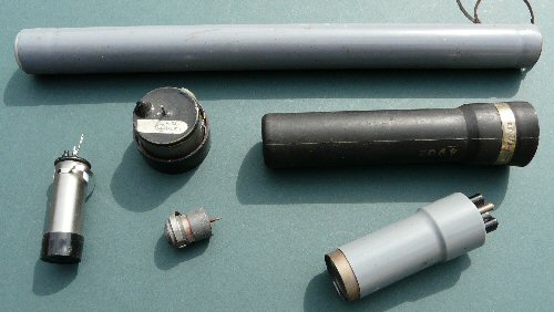
Geiger counter (GM) tubes come in all shapes and sizes. The long thin one at the top is about 20cm long,
the small one bottom left is the ZP1401 (see text below).
Introduction
The Geiger counter is a scientific instrument that can detect ionising radiation such as alpha and beta particles and gamma rays. It's capable of detecting a single particle and although relatively simple is thus exquisitely sensitive [1].
Sources of radiation
Radioactivity was discovered in 1896 by Henri Becquerel. Radioactive materials produce three different types of radiation: alpha (α) and beta (β) particles and gamma (γ) rays. The soil and rocks beneath our feet contain all sorts of radioactive elements which contribute to what is called the background radiation. It has been estimated that the top hundred yards of the earth's crust contains an average of 12,000 tons of uranium and thorium per square mile [2].
There are also radiation contributions from ionising particles produced by solar radiation hitting the upper atmosphere and also from cosmic rays, the origin of which is still partly a mystery, from our galaxy or even further out. So with this simple Geiger counter you can not only get a sense of the invisible radiation's around you from the Earth but also rather incredibly from distant galaxies and processes going on far out in the Cosmos!
How the Geiger counter works
The heart of the Geiger counter is the Geiger-Muller (GM) tube. This is usually a metal cylinder or jacket within which there is a metal wire or fine tube. Inside the tube is a gas at low pressure. In most cases one end is encapsulated with plastic while the other end has a fine mica window. The window maintains an air tight seal while providing a relatively easy access for highly ionising radiation such as alpha particles that would not easily pass through the dense metal of the jacket [3].
A high voltage (ca. 300 - 400V DC) is applied between the outer tube (-ve) and inner wire (+ve). As the outer jacket has a larger diameter than the inner wire or tube the electric field within the device is greater nearer the inner connection which makes it more sensitive towards the central part of the GM tube. The voltage is low enough however that the gas remains insulating (the plateau region of the GM tube charecteristics [3]) until an ionising radiation enters the device. A single particle entering the GM tube causes a cascade of ionisation's leading to the device creating a current pulse. The gas also contains a quenching chemical to stop the avalanche from being maintained indefinitely, allowing another particle to be detected shortly afterward. There is of course an upper limit to the number of ionisation events a particular type / design of GM tube can respond to [3].
Exquisite sensitivity
Imagine a single beta particle enters the tube and creates a click in the Geiger counter speaker. The beta particle might be a single electron. A click might be a 1mA pulse of 1/1000 second duration. This click will thus be equivalent to ca. 1/(1.6 x 10-19) x 1/1000 x 1/1000 i.e. about 1012 electrons moving. So in this case one electron has been transformed into a pulse of 1012 electrons. That's an effective 'gain' of 1,000,000,000,000 - quite impressive for such a simple device!
NOTE: The voltage on the ladder circuit is quite high and potentially dangerous. The voltage to the GM tube is via a large resistor and so this should not present any hazard but the capacitors will be charged up, and maintain their charge, for quite some time after the circuit has been turned off. So please take care not to pick up the circuit board in the palm of your hand even if you have disconnected the supply. I have shocked myself many times this way and you then have to spend time looking for the board you inadvertently threw (because of the shock) somewhere in your workshop!
More advanced detection
The basic circuit in Fig. 1 is fine for clicking an earpiece but will not drive a speaker or be able to operate a digital counter for example. The second circuit, Fig. 2, consists of a simple amplifier and timer (the left hand side 555) that boosts the GM pulse and creates a uniform pulse of constant period. This can be used to drive a pulse counter or speaker. The pulse is quite short (ca. 1ms) - long enough to provide a reliable signal for a counter but not too long that it would limit the detectable counting rate. A speaker can be connected via a 100R resistor to pin 3 of the 555 timer.
As this pulse is still quite short I have built in a second timer (right hand side 555) which then produces longer ca. 50ms pulses. You can use this to drive an LED. An LED wired to the first timer flashes too fast for the eye to see while the o/p of the second timer produces a clear flash for every click. Because the timing pulses are longer on the second timer this o/p will be limited in its maximum count rate.
Rough Science radioactivity
Hermione Cockburn was the Geologist in the Colorado series of Rough Science [6]. She travelled to Telluride (Colorado, USA, famous for its Uranium mines) to look for radioactive Rocks. She then built a cloud chamber to 'see' the ionising tracks the particles create [6]. It was great to get to know her on the series and so when I got back home I built her the Geiger counter described here as a 'thank you' present.
Everyday radioactivity
You can order small pieces of pitchblende (an ore of Uranium) from e-bay which will produce a nice response from the GM counter. Smoke detectors contain an isotope of Americium (Am-241) which is an alpha emitter. In the past thorium mantles were used for the material for camping lights (they give a very intense bright light) which are also slightly radioactive as are some faces of old luminous watches (ca. WWII).
Typical measurements
My GM tube (ca. 20mm diameter and 70 mm long) detects about 50-60 counts per minute where I live in Brighton which is built on the chalk Downland of Southern England (Sussex, UK) at sea level. A smaller volume tube like one used here [4] will interact with less background radiation and so produce proportionally less counts / min. Higher counts would be expected in areas where there are large amounts of radioactive granite for example such as in Cornwall and parts of Scotland. While filming the Rough Science Series in Silverton (Colorado 3000m asl) I took my Geiger counter along thinking that the readings would be very much increased but to my surprises I found similar results to those measured at home; ca. 50-60 counts / min.
My first scientific instrument
At school it was a dream of mine to make a Geiger counter. The Physics teacher and I even submitted designs for one for a national school competition one year. On the last day of school he gave me an old GM tube saying "I don't think this works but you might like to experiment with it" - this was very, very kind.
In my first year of the Worthing Sixth Form College walking to-and-fro between my home I started planning in my mind exactly what I was going to do with the tube, the circuit design and even the constructional layout. One afternoon I suddenly stopped procrastinating and had the thought "why don't I make it right now? What's stopping me making it right now?
. Nothing!" Over the next hour I got down to making the device and my dream literally became reality - it was really wonderful and quite magical to see it appear.
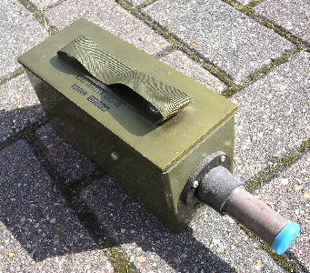
In my walking, slightly day-dreaming plans I had thought through many of the possible problems that might come up, how to test each stage and how to best layout the design. With all this preparation when I finally made the effort to make the Geiger counter it almost felt like it built itself. My first circuit was similar to that shown in the basic design (Fig. 1) except that it was made mostly from scrap parts cobbled together. I used an old plastic army battery box for the case. It's still working 25 years or so later ....
Travels with my Geiger counter
I gave a talk on my homemade Geiger counter while studying for my Physics degree at Surrey University. That weekend I went home on the train and had to change at Gatwick and having a long wait I decided to wander around the airport to fill in time. I must have looked suspicious as I was eventually stopped by two Police men who questioned me. They asked me what was in my bag and being rather annoyed at all their questions I barked back "a Geiger counter of course!" at which point they took me into a room and asked me lots and lots and lots of questions. I missed many trains home. Of course I DID have a Geiger counter in my bag and a homemade one at that. It took a while to sort that one out ... and that was in 1988, God knows what would happen now .....
Recent changes / modifications
I noticed that the 555 on the HT generator for the GM tube runs a little hot. I added a 15R resistor between the 555 output and the LT700 transformer to limit the pulse current into the transformer. Now the 555 runs cool.
I have added Fig. 1b in November 2012. I built this alternative high voltage supply to test the tube responce with a different supply as I was slightly worried that Fig.1a o/p was varying. Fig.1b is simplier than the 555 circuit, takes less current and seems to provide a higher current o/p at 450V. I think its a better circuit overall.
June 2013: After making several of the Geiger counter high voltage generator circuits I have noticed a few problems. The audio transformer used to generate the HV seem to vary in spec from device to device. The result is that the voltage developed by the circuit is sometimes rather low ca. 200V (9V supply) to run a Geiger tube. To get a higher voltage (ca. 400V) the resonant frequency capacitor (across the transformer) and the feedback capacitor can be varied to peak the circuit. The original circuit had C1 = C2 = 47nf but I found that the changing the transformer cap to 22nf and the feedback cap to 10nf was more effective. The drive resistor to the base of 10k can also be reduced to say 4k7. I usually power the circuit from a 9V supply and then derive the 5V for the logic boards from this.
References and links
[1] For a short movie about the Geiger counter see: Vega minimovies
[2] See page 448 of Isaac Asimov's New Guide to Science, Penguin, 1984. ISBN 0 14 007621 2
[3] See wiki GM tube page: Wiki Geiger page
[4] GM tube type ZP1401 cost ca. È57-00 + vat (ca. June 2010) new and are available from Centronics, see:
Centronics web site
Alrad web site (uk distributor of Centronics GM tubes)
[5] For diode ladder multiplier circuits see: diode multipliers
[6] The sixth BBC / OU Rough Science TV series set in Silverton, Colorado, USA, see: RS six
.........................
JPH, June 2010
THE CREATIVE SCIENCE CENTRE
home | diary | whats on | CSC summary | latest news