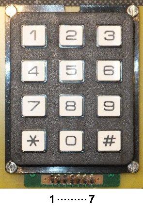
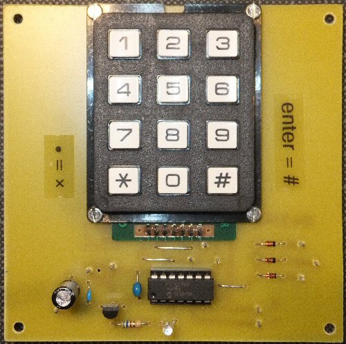
G4JNT PIC project for the FT817 transceiver
direct frequency entry via keypad


FT817 kepad entry unit

G4JNT
site
3D printed
FT817 brackets
3D printed
edge template
more
soon
my radio
page
back to
PIC page


This is a Andy Talbot project (see links above). If you go to his site you can download a zip files with the asm, hex files and PDFs (Note: There is a typo on the Sept. 2014 circuit PDF as pin 11 is marked twice (one is pin 12)). This is my own pcb arrangement but the circuit and programming are his work. I put up this page to advertise his interesting projects but also discuss some problems I encountered, I hope it will be of help to others.

8-pin min DIN lead
I made use of a 2m lead with a 8-pin mini din plug on each end as they go for only a few pounds on e-bay. My intention was to cut the lead in two so then I would have a couple of useful ready-wired leads. However the leads I purchased were a 'cross-over' type so the coloured wires that go to one of the 8-pin plugs do not mirror all the pins of the other plug. You might find that the all important FT817 'RS232' Rx and Tx connections are connected with different colours on the two plugs. Details below:

details of the 8 pin plug and socket

FT817 ACC
(socket view)
pin No. first 8-pin plug
(plug view)
second 8-pin plug
(plug view)
POWER 1 red brown
TX GND 2 brown red
RX D 3 green orange
TX D 4 yellow yellow
GND 5 orange green
TX INH 6 black blue
ALC 7 violot violet
BAND DATA 8 blue black


Note: You can also buy a 8-pin mini Din to 9-pin D sockets (e.g. like a RS232 lead).
I brought a couple of these from different suppliers but in both cases I found they only had three or four pins actually connected and so were not suitable for this FT817 project.


FT817 kepad entry unit
12 button KeyPad
I had a 12 button telephone-style keypad that I think came from Maplin electronics a few years ago. It looked identical to the one Andy used but it didnt work correctly. Some keys didn't respond on the radio and these keys did not flash the LED. Obviously my particular keypad had completely different pin connctions (on the multiway connector) than the one Andy used. It took me a while to sort this out. If you find you have the same problem you will have to work out the network of key connections yourself, I hope my guide helps (I am not sure how many keypad versions 'out there'). I have listed below which of my keypad connections went to which PIC pins and how they compare with Andy's circuit:

Keypad connections: keypad pin to PIC pin
keyboard pin* PIC (mine) PIC (G4JNT)
1 (left) 12 11
2 10 12
3 13 13
4 7 7
5 11 8
6 8 9
7 (right) 9 10

* Keypad pin numbering: G4JNT's numbering and my keypad version.
Mine are marked in the following way: looking down on the 12 keys, the multiway connector sticks out below the keys
pin '1' is on left hand side, the next is '2' ... going through to '7' on the right hand side.


Extra Funtions
Andy has provided connections for three extra push button switches or toggles. These could be used to provide special fuctions at a later date e.g. push button Tx etc. At some stage I will make use of these by modifying his assembly code. I would also like to add an LCD display showing the current FT817 frequency. As I plan to use the transceiver with a 23cm transverter. I would like to show the converted frequency (so I don't have to do the calculation in my head) and also perhaps provide a software correction to accomodate any transverter LO offsets that might exist i my old transverter. I may need a higher spec PIC for these additions.

THE CREATIVE SCIENCE CENTRE


Dr Jonathan Hare University of Sussex, Brighton.
e-mail: j.p.hare@sussex.ac.uk

home | diary | whats on | CSC summary | latest news