Useful templates

The 3D printer is really useful for making up jigs and templates to help mark things out for drilling and / or to help with doing repetitive jobs that need to be done accurately. I will load up the files at some point but this page is really to show the sort of things that can be done as you will probably want to design your own template for your particular job. I will be adding different template designs as I get time to write them up.


series


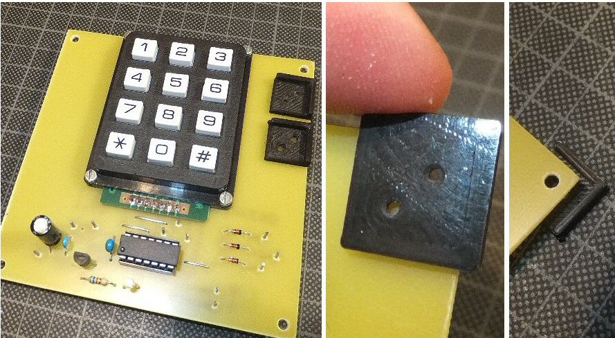
I made up a device that fits over the corners of a pcb so you can quickly and accurately mark-out a drill hole. Ideally you want to do this before etching or assembling the components onto the circuit board but in this example there was enough space to be able to use the template after I had completed the pcb (btw its a G4JNT direct frequency entry device for a FT817 radio). I printed two templates; one with 1mm diameter holes, the other with 3mm diameter (M3) holes - it took less than 10 mins to print them out. Both have a lip that fits over the two edges of a corner thus locating the device and the holes. The first template with the 1mm holes can be used to mark-out the board near to the edge or slightly further in. The second with the 3mm holes could be used to directly drill through the board (you can see both types resting on the pcb on the left hand photo).


series

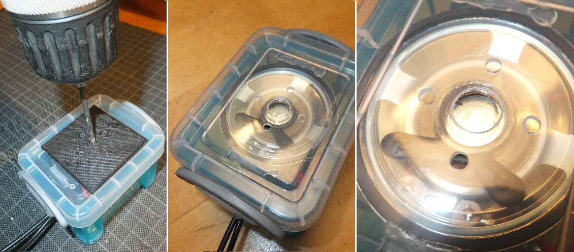
In the second example I needed to make twenty five 555 oscillator tone generators for the Brighton Science Festival Neuron workshops for schools. I had 25 front panel speaker grilles to drill out and they needed to be done fairly accurately to look presentable. I made up a 3D printed template so that I could drill five 3mm holes into the front case (four holes around a central hole). The result was a really quick and effective way of accurately drilling all the cases. The template saved a lot of time as I did not need to separately mark-up all the front cases, I simply held the template onto the front of each case and drilled through the five holes and then afterward drill out the center hole to about 8mm. Note the photo apparently shows me drilling into the lids while they are on the completed unit ... I didnt actually do this the photo is just to show the template in position. I actually drilled each lid seperately on a piece of scrap MDF.

combined template

A useful template
I like making circuits and then building them into enclosures to complete the project. I often have to cut-out holes for plugs and sockets or for panel displays and meters. Single sockets, switches and waffer switches are simple enough with a well placed drill hole, but the more complex sockets and devices involve carefull marking out of the metal work or plastic using masking tape or an over head projector (OHP) pen before drilling, cutting and filing. Here I describe a template which I hope will be useful to speed-up the marking out process and help reduce errors or mistakes. I have carefully measured a few things that I often use and created a template with holes at the main points that need to be marked.

One of the really nice things about the combination of using a 3D printer with software such as OpenScad is that you can easily design parts with very well defined dimensions and sizes. The printing nozzle actually extrudes a thin plastic thread so you have to take this into consideration when making parts. But bearing this in mind you can create things to a fairly good spec.

combined template parts

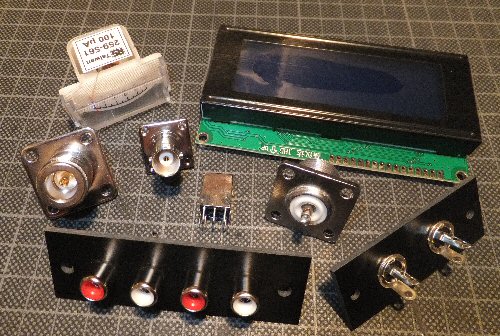
My template has the basic marking points for the following:
BNC, SO239 and N-type sockets (four bolt hole types), 2-way and 4-way phono sockets and the pin and solder tag positions for a typical IF transformer / TOKO radio coil. I have also included bolt holes and the rectangular cut-out profiles for a four line LCD display and a small 100uA panel meter. In the BNC or SO239 sockets for example I have marked out the positions of the four bolt holes that form a square around the center. You can use a center punch or a fine marker pen for the four bolt holes (e.g. four 2.5M for the BNC and four 3M for the SO239 and N-type). This fifth, central point marks where you need to drill a larger hole to take the central part of the socket. The size will depend on the type of socket you use and if it will sit on the outside of the panel or go through the panel from the inside etc.

Final remarks
You will no doubt want to create templates for the things you use. I have written the code so that you can easily take out a particular template if a) you don't require the other objects or b) the combined template is too large to use / wont go in the available space etc. In this case simply copy the part of the code you need and then remove the 'translate' command (used to spread them around the large template). The print quality will depend on the particular filament you use and the state of your printing nozzle so you may have to print the holes slightly larger (or perhaps smaller) to the ones I have chosen. 0.8 mm often produced a templete where some of the holes closed up or indistict so I used r =1 mm. In principle that should produce a 2mm diameter hole but because of the filament thickness its closer to 1mm on my machine. It is easy to change the hole size because I have used a common constant for this value. So you also need to copy this into any template you decide to extract from the combined template. I sometimes opened out the holes slightly using 1 or 1.5 mm drill bit and a stiff brush can be used to remove any plastic swarf.

back to 3D page

THE CREATIVE SCIENCE CENTRE


Dr Jonathan Hare University of Sussex, Brighton.
e-mail: j.p.hare@sussex.ac.uk

home | diary | whats on | CSC summary | latest news