Three element collinear array for the 2m amateur band
using 3D printed parts

2m 3 element collinear 2m 3 element collinear
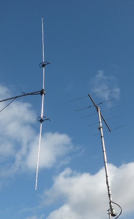
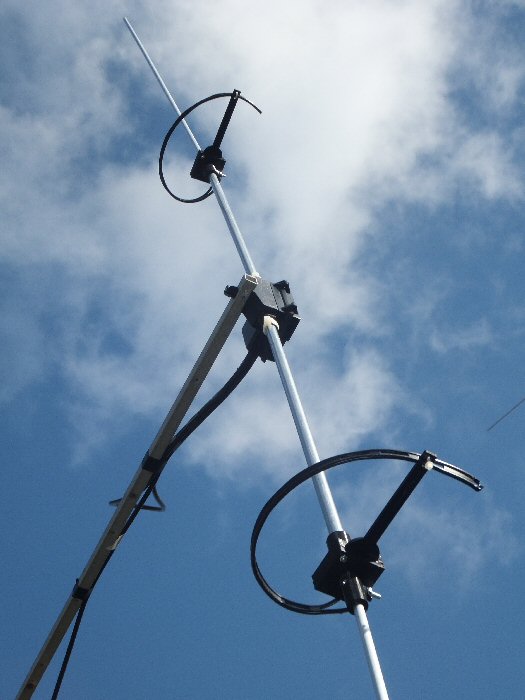
Photo 1: The vertically mounted 2m band experimental three element collinear array shown near a 5 element 2m Yagi for comparison.

This is a three element collinear array for the 2m amateur band. It is three half-wave dipoles driven in-phase. It is made from a central standard half wave dipole with a halfwave element attached to each end. You can't of course simply join the extra elements onto the dipole as this would simply push the resonance to longer wavelengths. In order for each of the elements to 'work together' they need to be fed correctly in phase. We do this using sections of feeder between the end of one element and the beginning of the next. These delay lines (DL) make sure that the wave arrives at the next element in the correct phase so that the overall power being radiated adds together. A quarter wave piece of feeder shorted at the end will delay the wave by half a cycle by the time the wave has travelled along and back, from the end of one element, out to the short and then back again to feed the next element. So the DL's need to be a quarter of a wavelength long.

2m 3 element collinear
Diagram of the three element collinear array.

This three element array is center fed. The impedance at the center is a few hundred ohms and so can be feed with a 4:1 coax balun to balance and match the antenna to 50 ohm cable. In principle such an antenna should have a power gain of about 3dB over a half wave dipole. When mounted vertically it will radiate an omni-directional signal.3D printingThe exciting thing about a 3D printer is that you can easily print out parts for an experimental antenna such as this. Although the plastic is a good electrical insulator and should be UV stable (black is better than white) it probably won't stand up to winter gales (although you can easily print out spares in case of breakage's). The antenna would however be suitable in a sheltered spot, for portable use or in a loft space for example. I made them to learn about phasing and simply to play with antenna ideas.

The parts
I brought an FM broadcast band dipole very cheaply from e-bay. It included the mast clamps, the two 12mm Aluminium dipole tubes and a water proof box for the coax connection. I cut the tubes down to suit 145 MHz and removed the FM band balun in the box. I used this dipole for a number of years as a receiving antenna and a 'dipole' reference to compare with other antennas. In order to modify it to take the two extra halfwave elements at each end, I needed to make up some insulating holders that could take the ends of the aluminium tubes. I made up these insulating connections to go on to the ends of the dipole tubes using my 3D printer. The parts that went into the dipole ends consisted of a 4.5 cm long cylinder having a central hole connected to a square fixing flange (with four fixing holes for 3M bolts). The cylinder also has a small and large hole opposite each other so that a bolt can be put through to secure the tubes and solder tags to make electrical connection for the DL sections. Similar devices were printed to attach to the two outer elements. As I used 6 mm diameter tube for these the support cylinder was proportionally smaller diameter but it had the same square flange at the end. Again two holes where added to the side for support and connection to solder tags for the quarter wave sections. Two support arms for the DL sections were also 3D printed. These were basically a long thin (4 mm thick) rectangular arm with a square fixing flange. It was sandwiched between the two tube holders and the three secured together using four M3 bolts (2 bolts will suffice). This arrangement of the two rod and DL holders was repeated for the third element in the array. Once the DL sections have been attached and the correct length established (see below) they can be curved around so that the end of the arm fits into the slots on the ribbon cable. A cable-tye holds this in place. This is a neat way of securing the DL sections.

2m 3 element collinear 2m 3 element collinear
Photo 2: Close up of the lower of the two insulating 3D printed Delay Line and element supports. It is made of three sections sandwiched together:
i) 12mm ii) 6mm rod support and iii) a central DL support. Each has square fixing flanges which allows all three to be bolted securely together.


Matching and SWR
Collinear arrays are broad-band antennas which makes them simple to construct and tune. If the elements are not quite the correct length their reactance can probably be partly accommodated for in the DL lines. I expect that the fields from the three elements may well interact, helping to broaden the response of the antenna as I found that none of the lengths seemed to be very critical. In this prototype I used 1m lengths of tubes for the two extra halfwave elements as this was the length that they came in. This is a little long for 145 MHz and so the center of the antenna resonance was a little 'below' 2m - it didn't seem to effect the performance once the 4:1 was attached and the quarter wave sections adjusted. I fed the antenna at the center with a 4:1 coax balun made from a halfwave length (81 cm) section of 50 ohm cable connected in the usual way to the main coax cable. I used mini 8 (RG-8X or RG8XT) which has a relatively low loss and is very easy to handle. I used a 2 wavelength lead (2 x 300 / 145 x 0.78 (cable velocity factor) = 325 cm) so that I could test out the antenna. A multiple number of halfwave lengths of line should not introduce unwanted reactance into the system. This length also provided a useful run to connect to a longer length of RG213 once the antenna was put on the mast. A quarter wave at 2m should be close to 300/(145 x 4) = 52 cm in length. However the velocity factor (VF) of the open wire feeder needs to be taken into consideration and this will reduce the length. I used 300 ohm twin feeder with a quoted VF of 80% but I have a feeling that this value depends on frequency, so you have to experiment a bit with various lengths to get it right. I made up 69, 49, 42 cm lengths. Finding the 42 was best I further reduced it to 36 cm and got an SWR of less than 1.5:1 over a wide range so I left it there (this would give a VF of 36 / 52 = 0.70 or 70%). SWR plots provide a very rough guide to the antenna response. Measurements were made with a MFJ-269 antenna analyser with the antenna mounted horizontal about 2m above ground using the 2 wavelength feed of mini 8 cable directly into the analyser. The antenna response is quite broad. It would probably be worth pruning the length of the two outer elements from 100 to 98 cm or so, to bring them more into the center of the 2m band (145 MHz) but I doubt it will make a great deal of difference to the performance 'on air'. As this is an experimental set-up I left them as they are in case I want to use them for something else (e.g. 2m Yagi reflector elements that are about 1m long).

Off-set mounting
As the antenna was to be mounted vertically for my tests and it is center fed, I needed to take the feeder perpendicularly away from the antenna as far as I practical before sending it back down the mast to ground level. The antenna also needs to be away from the metallic mast so I had to use a horizontal mast support. Note: this meant the whole array was not balanced very well on the mast.

Results
I have been using home-made antennas on the local 2m Worthing & District Radio club FM Monday night net for several months. At first I used a quarter wave ground plane (GP) antenna and then moved onto a 5/8 wave vertical (both partly constructed from 3D printed parts). As expected the 5/8 performed a little better than the GP. Two of the net group are ca. 20-30 miles away (and the other side of the hill to me) and so I receive their signals very weekly. One Station on these antennas was just strong enough for me to hear that a carrier was present but not strong enough for me to hear what is being said. So it was great to discover that this new antenna (at the same height) brought this signal completely out of the noise so that two way communication was now possible. One issue that I now have is that the local Brighton repeater. It is only about a mile away and is a direct line of sight. When the repeater transmits I now lose S-points on the weaker signals and so my IC706 receiver is struggling with the strong nearby signals.I have installed a quality band pass filter to stop local data pulses causing receive problems which works very well but the device won't of course help with strong in-band signals. I may have to live with this problem. It is worth while making sure I switch out the radios internal pre-amp .

Up-date: I have now swapped this antenna for a vertical 5 element ZL special and with its good front to back ratio I have solved the problem.

Ideas for further work
Now that I have got this antenna working I am interested in making up an all-wire version. In other words I would not need the costly aluminium tube but use wire intsead. I might then be able to hang , suspend the antenna to the side of a high mast. I could then experiment with a 5 or 7 element array to get better gain. I will use the 3D printer to create in-wire DL supports rather than using Al pole supported devices. It might be possible to create all the DL and elements for a full collinear array from one piece of wire correctly bent using 3D printed formers.

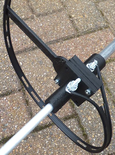
Tube holder I
".stl" file
".g" file
".scad" file
Tube holder II
".stl" file
".g" file
".scad" file
Delay Line holder
".stl" file
".g" file
".scad" file
my radio
page
my antenna
page
back to
3D page


THE CREATIVE SCIENCE CENTRE


Dr Jonathan Hare University of Sussex, Brighton.
e-mail: j.p.hare@sussex.ac.uk

home | diary | whats on | CSC summary | latest news