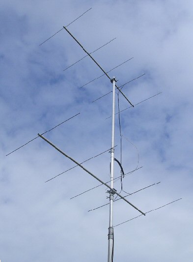
2 x 5 Element Yagi array for 144MHz
Note: these antennas are based on an old ARRL design [ref. 1, see single yagi page below). It might be a bit ancient but I like it because it contains so many classic antenna and transmission line fundamentals all wrapped up in one design. It works really well to!
There are some advantages to stacking yagis rather than using say an (equivalent number of element) long yagi. As its quite possible to make any piece of wire have a good SWR with suitable matching. So a good SWR on a long yagi does not necessarily imply that it will have good gain or work well. Smaller yagis are often less fussy about exact dimensions and have a greater bandwidth than a long yagi. Staking small yagis can therefore produce a better overall antanna array than a long yagi.
Secondly a staked system has a smaller turning circle requiring a lighter support structure and finally if you live in a suburban plot they look less obtrusive in the air or on the chimney.
A 2 x 5 antenna may have similar basic gain to say a well made 10 element long yagi but with slightly different distribution of azimuth and altitude gain. A single yagi may only produce one forward lobe in the vertical axis (azimuth) while stacking them may produce a few. Some of these lobes may lie in favourable propagation angles and so produce interesting advantages over a single lobe.
For two similar stations close together and running similar powers I have found the 2 x 5 often seemed to performed better than one long 10 element yagi.
Construction
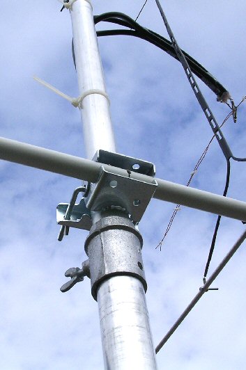
Two identical 5 element yagis were constructed as described. Cheap universal TV antenna type brackets were used to hold them in place upon an aluminium mast suitably separated.
An open wire feed system was used to feed the two yagi, as described in the original article. I used 208cm of slotted 300 ohm ribbon which at each end were cut down the middle 15cm or so and spread out to meet the connections either side of the center of the yagi dipoles (ca. 8cm either side of the center). I used solder tags bolts and small butterfly nuts which can be quickly taken to pieces / assembled for portable work.
At the halfway mark along the slotted feeder a section of home made half wave matching section (107cm long) was attached. I used 1 mm copper wire (as it was very similar to the diameter of the slotted feeder wire) and spaced it the same width as the 300 ohm slotted feeder, ca. 1 cm.
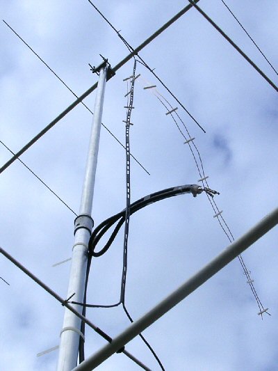
Using a 4:1 coax balun it is very straight forward to get a good match using an antenna analyser / SWR meter ... trying various places along the half wave section in conjunction with a shorting bar moved up from the furthest end.
In my particular set up I found the distance to connect the 4:1 balun along the half wave section (between the two yagis) was about 84cm (ca. 22cm from the shorting bar) with a shorting bar distance from the end of only about 1cm.
For a 1m coax line (RG8) very close to the balun a good SWR (1.6:1 or better) was obtained between 144.00 to 146.00 MHz (I did not find much difference using a 10 m run of RG213). Swapping over the yagis or changing over to other yagis (two other from the 4 x 5) didnt make any difference.
The plastic boom were made from household plumbing waist pipe. When stored or for transport the 5 elements for each yagi can be stored inside these tubes, rubber bungs or tape can be used to secure them.
For portable operation once the mast is up, the 2 x 5 can be assembled and on the air in just a few minuets.
link to 5 elemant yagi page
link to 4 x 5 element yagi page
home | diary | whats on | CSC summary | latest news