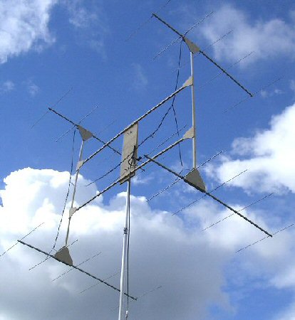
4 x 5 Element Yagi array for 144MHz
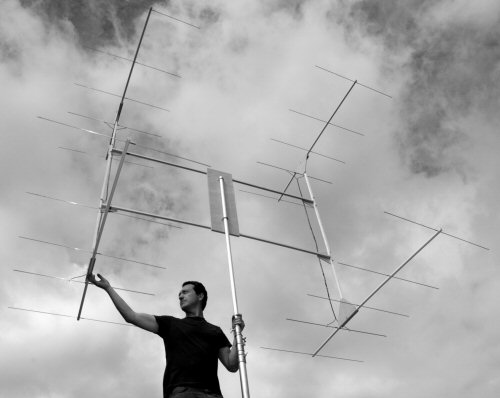
Note: these antennas are based on an old ARRL design [ref. 1, see single yagi page below). It might be a bit ancient but I like it because it contains so many classic antenna and transmission line fundamentals all wrapped up in one design. It works really well to!
Construction
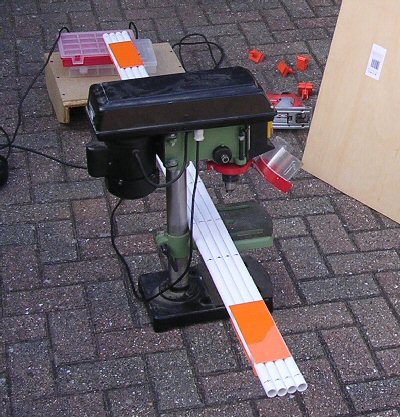
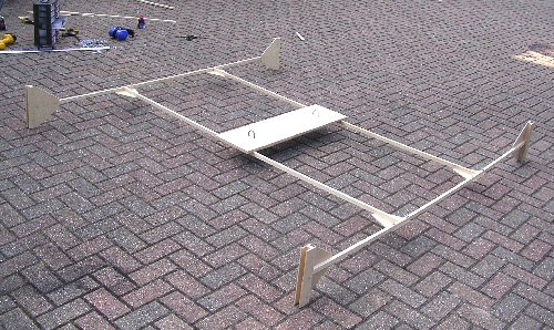
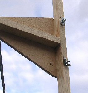
Four identical 5 element yagis were constructed from plastic water / waste pipe. I taped the tubes up and secured them side by side and then drilled them with a pillar drill. Unlike the 2 x 5 array which was supported on a vertical mast here I built a simple wooden H frame with small triangular boom supports to help hold each yagi in place. A single bolt and butterfly nut being sufficient to hold each antenna in place and two bolts and butterfly nuts to hold the side cross bars to the yagi support up-rights.
An open wire feed system was used as described in the original article. I used 82" (208 cm) slotted 300 ohm ribbon cut down the last 15cm or so at each end and then spread out to meet the connections to the yagi dipoles (ca. 8cm either side of the center). I used solder tags, bolts and small butterfly nuts to hold in place but which can be quickly taken to pieces / assembled for portable work. Two identical harnesses were made for the two sets of 2 x 5 and a third connected the mid point of these two feeders.

I marked the left hand side of each feeder at each of the yagi dipole centers so that each time the antenna was assembled it was clear which went where so that the phasing wound always be correct. On assembly the central feeder was also checked to make sure it was not twisted.
At the halfway mark of this third section a home made half wave feeder (107cm long) was soldered and used as the half wave matching section. I used 1 mm copper wire as it was very similar to the slotted feeder wire diameter and space it the same width as the 300 ohm slotted feeder, ca. 1 cm.
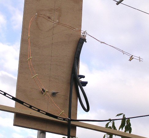
Using a 4:1 coax balun it is very straight forward to get a good match using an antenna analyser (SWR meter) and trying various placed along the half wave section and using a shorting bar moved up from the furthest end.
In my particular set up I found the position for the 4:1 balun feedpoint was about 77cm from the point where the half wave section connects to the slotted feeder between the two vertical feeders (supplying the two sets of yagi's) which was also about 23cm from the shorting bar. The shorting bar distance from the end was about 5cm.
With a 1 m coax line (RG8) close to the balun a good SWR (1.6:1 or better) was obtained between 144.00 to 146.00 MHz (I did not find much difference using a 10 m run of RG213).
The plastic boom were made from household plumbing waist pipe. When stored or for transport the 5 elements for each yagi can be stored inside these tubes, rubber bungs or tape can be used to secure them. For portable operation once the mast is up, the 4 x 5 can be assembled and on the air in about 20 minuets depending of course on the particular set up / situation. There is a considerable wind laoding on this large structure so you need to be prepared for this in your mast / support design.
link to 5 elemant yagi page
link to 2 x 5 element yagi page
home | diary | whats on | CSC summary | latest news