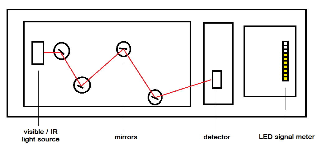
Basic diagram of the light beam demonstration showing the light source (left hand side) which can be set for visible or Infrared light and the mirrors that are used to reflect the light onto the detector (to the right). Both the light source and detector have magnet bases that allow them to be attached to the metal covered board where they can easily be adjusted to any position or angle. The number of LEDs that light the detector electronics (far right) is dependant on the strength of the signal making its way through the mirror refections. - there are two sensitivity settings (high and low).
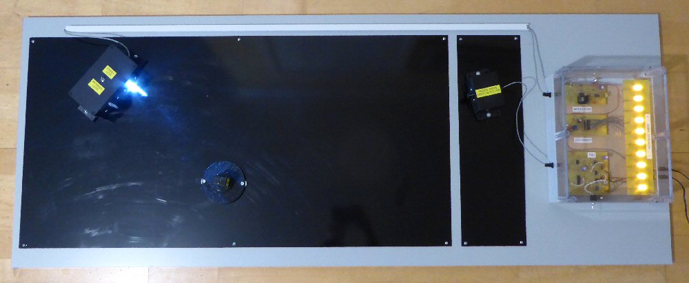
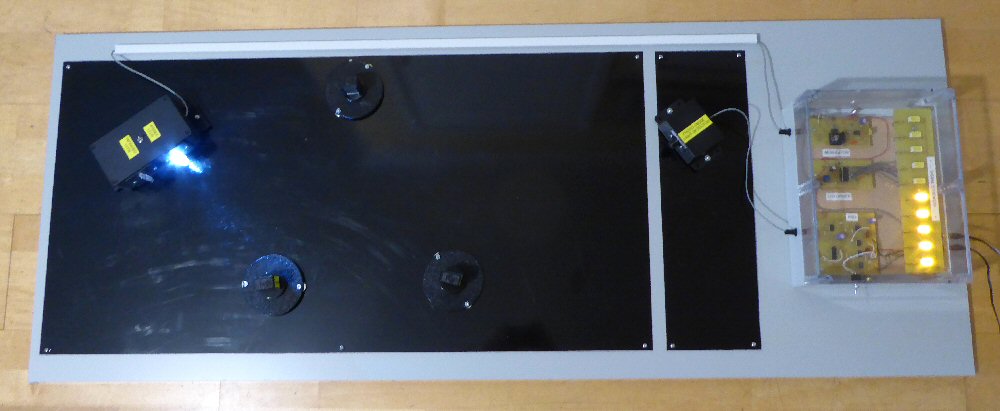
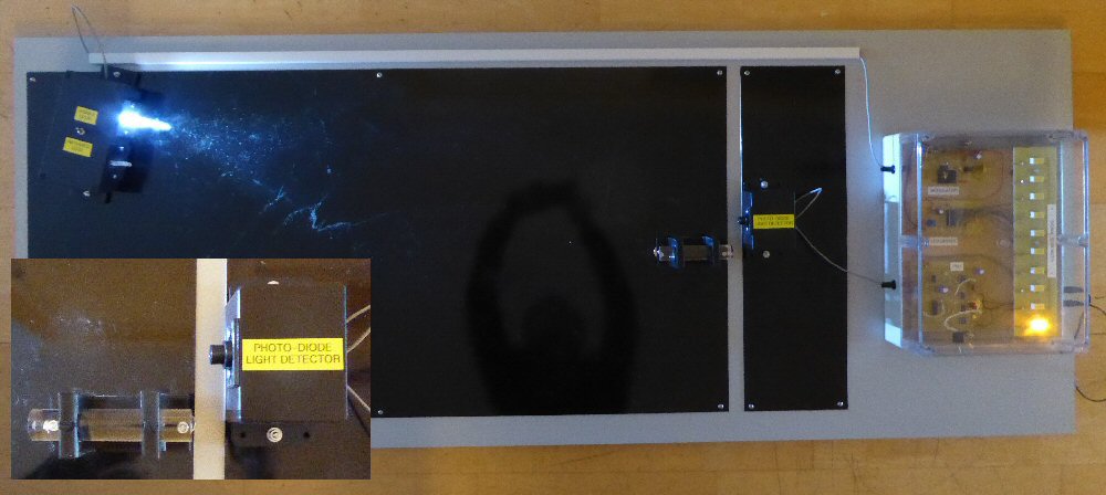
In these pictures the light source (left hand side) has been switched to visible light and we are only using one mirror to reflect the light onto the detector (to the right). Both the light source and detector have magnetic bases that allows them to be easily adjusted for position and angle.
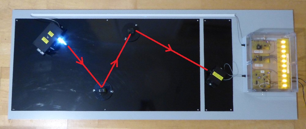
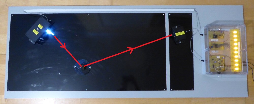
As above but using two mirrors to reflect the light onto the detector.
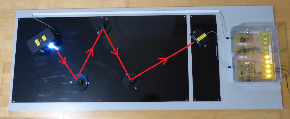
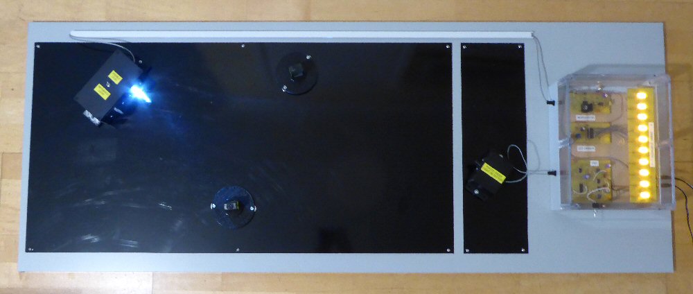
As above but using three mirrors to reflect the light onto the detector.
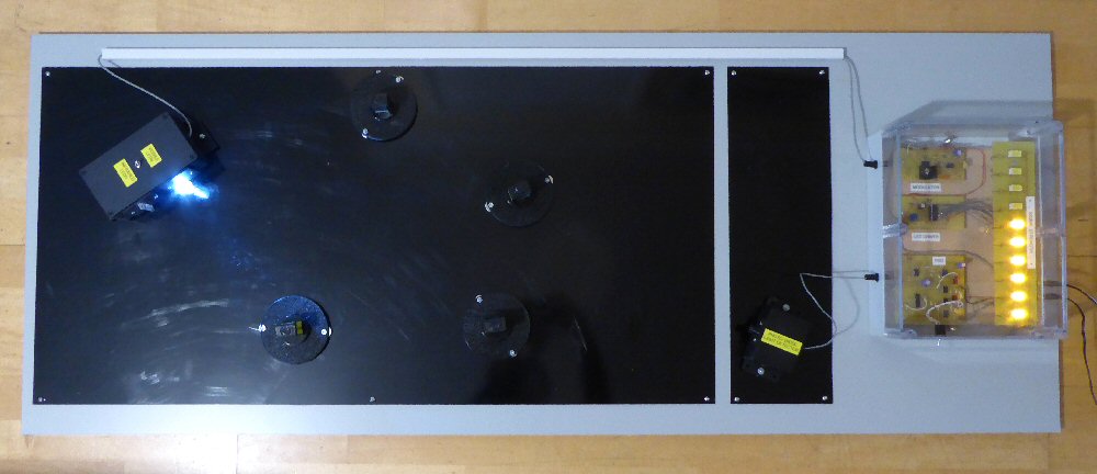
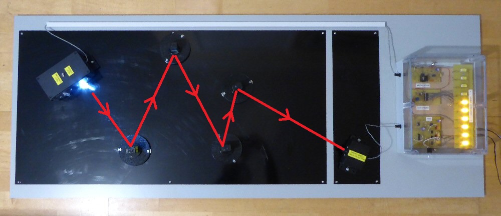
As above but using four mirrors to reflect the light onto the detector.
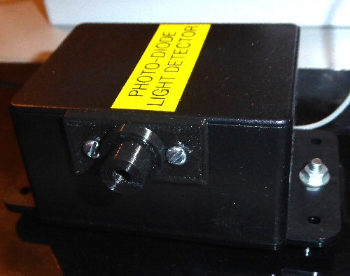
The photo diode detector in its box - you can see the collar in front of the detector which helps to screen out unwanted light and collimate the responce of the detector.
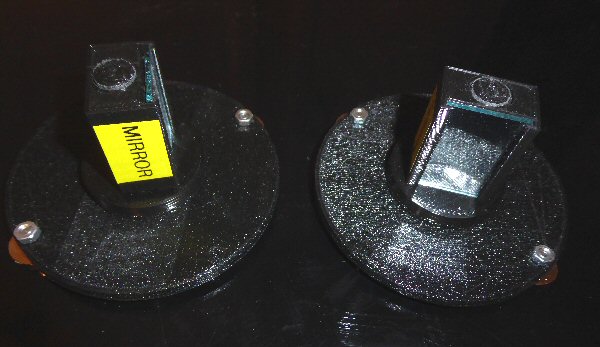
Two mirrors in their 3D printed mirror supports.
The mirrors rotate on the mount so they can be easily adjusted to the correct angle to reflect the light beam.
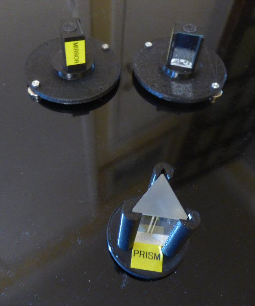
Picture of the magnetic mounted prism and mirrors.
The mirrors and prism rotate so can be easily adjusted for the correct angle.
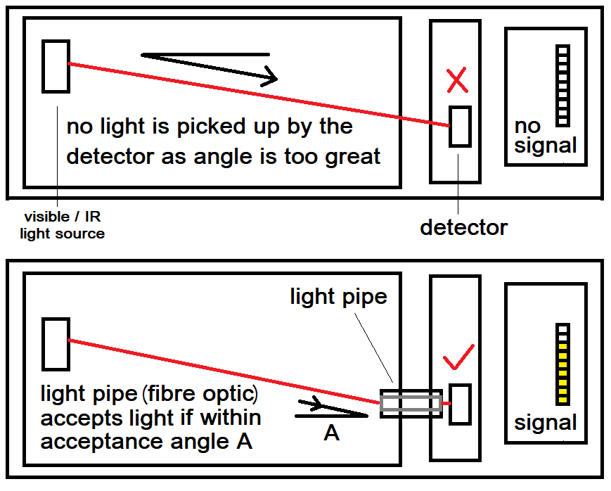
Diagram showing how a light beam arriving into the light pipe (within a critical angle) will be internally reflected along it
and delivered to the light detector. In contrast very little signal is detected without the light pipe for this angle. Also see pictures below.
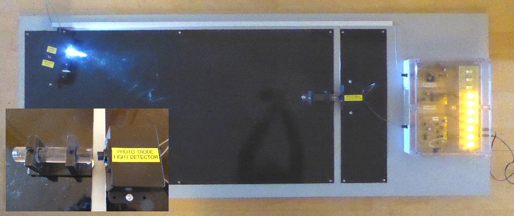
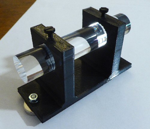
Close up of the 3D printed light pipe stand. The light pipe is a 10cm long piece of Perspex with polished ends.
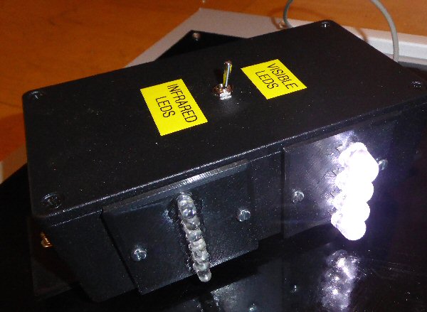
The light source box: visible white light or Infrared light can be selected.
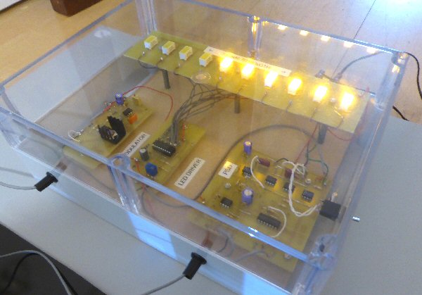
Picture showing the electronics in the clear plastic box.
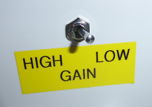
The electronics can be set for low or high gain.
High gain is needed when the signal low such when the light beam is past though many optical devices e.g. four mirrors and the prism.
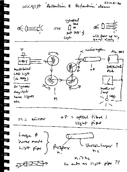
Some early notebook apparatus design ideas I
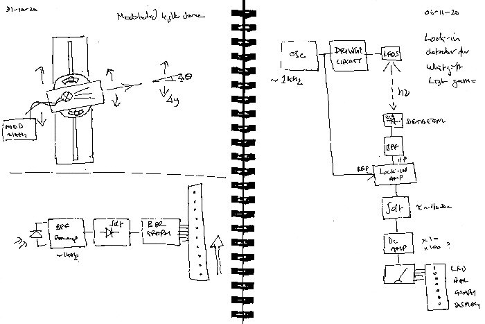
Some early notebook apparatus design ideas II
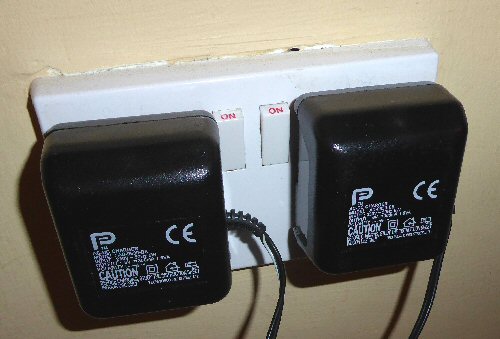
The equipment only needs these two small 9V DC power supplies for all the electronics.
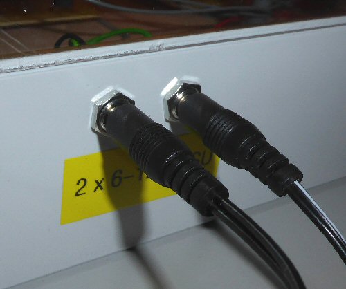
Two DC input sockets from the low voltage mains power supplies