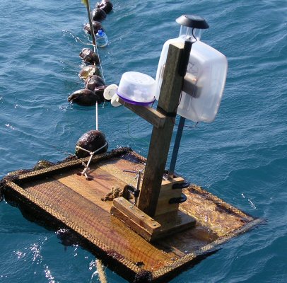
The Rough Science homemade raft and wave generator bobbing up and down, and side to side, making electricity
(Note: this article has been published: Starting to experiment with wave power
Jonathan Hare and Ellen McCallie 2005 Phys. Educ. 40 574-578 reproduced here by permission of IOP)
The Problem of Energy
Modern society consumes a great deal of energy; most of which is from non-renewable sources [1]. One way to stimulate discussion and inspire our children into thinking about energy issues (for it is they who will find solutions) is to develop projects around them. Scanning the internet and teachers' resources much can be found on alternative energies such as wind and solar power but there is less information about wave power.
What follows are some simple ideas and project designs to allow pupils to start to experiment with wave power to generate electricity. The design was first explored during a Rough Science challenge as part of the fifth series set in Zanzibar (BBC2 March 2005 [2]). Hints and tips for budding experimenters are also included.
The power of waves
Wind creates waves that travel across vast oceans. These waves also convey vast amounts of energy. Water waves are a rather complex combination of longitudinal (e.g. like sound) waves and transverse (e.g. like rope or Electromagnetic) waves (see web site listing below for some nice animations of the different types of waves). If we look at any part of the water as a wave travels through, we see that they move in little circles rather than just up and down. The radius of these circular motions increasing as the water depth becomes shallower, e.g. as the wave heads into the shore and so shallower water. So a raft floating on the sea will not only go up and down but will also be moved forward and backward as waves go past. If you are out on the seas in a little boat or even an ocean liner it is clear that there is a great deal of power in the waves!
Generating Electricity
In an earlier article [3] we gave an account of a simple electrical generator (the Shake-a-gen) which produced electricity by Faraday Induction. Here a changing magnetic field induces a voltage into a nearby coil of wire. In this simple generator Faraday induction takes place when the device is shaken (the motion of the magnet continuously changes the magnetic field interacting with the coils of wire). This is a very simple way to make useful amounts of electricity and we will use it to make our own experimental wave power generator.
The maximum voltage V induced in a coil of wire whose wire turns intersect a changing magnetic field is given by:
V = A x N x dB/dT
V = generator output voltage (volts)
A = cross sectional area of the coil of radius r (A =πr² in meters²)
N = number of turns of wire in the coil
dB/dT = the rate of change of the magnetic field (Tesla / sec)
There are a number of ways we can harness power from the sea and we will of course be making use of the continuous stream of waves rather than a single wave. However, we can see from the equations that in order to get the most voltage from the simple generator we need the magnetic field changes (dB/dT) to be as large (fast) as possible. But waves are slow things.
Some commercial wave power designs have used the slow wave movement to squeeze air from a large flexible floating chamber through a narrow restriction and so convert the relatively slow flow into a fast moving steam of air. This is then used to drive a turbine / generator. In this way the slow wave movement is converted into fast moving air to drive the generator effectively (quickly).
A Rough Science Wave Generator
In order to have the maximum scope for experimentation and innovation we have chosen in our Rough Science design to have the simplest arrangement possible to harness some of the power of the sea. A simple design might also be more likely to keep working for extended periods.
In this design we fix the apparatus to a floating raft making use of the constant movement of the surface of the water (by the waves and / or swell) to constantly move the magnets in and out of coils of wire (like a slow shake-a-gen) and thus generate electricity.
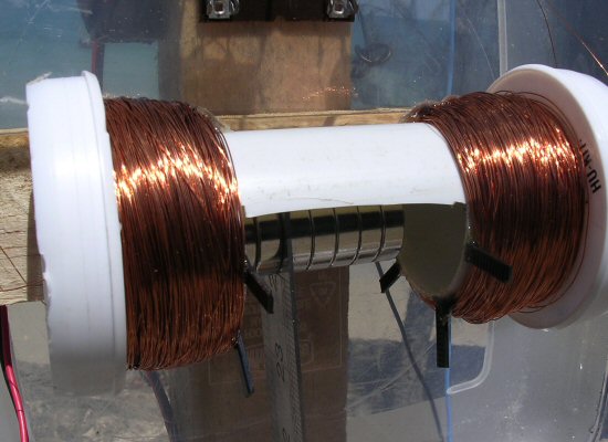
The coils were wound on the ends of a short piece of plastic drain pipe (see picture). This had a section cut from its middle, large enough so that the ruler supported magnets could be easily inserted and so that they were free to move. Because the magnets move back and forth, we can have coils on either side of the set of magnets, thus generating electricity in each coil set. The voltage output from each coil is dependant on the speed and direction of the magnets movement and so produces AC (alternating current).
In the program we used all the magnets given to us in the kit (about 10) but the device will work even with just two magnets (depending on their strength of course), but some careful positioning of the coils around these magnets (to get the maximum voltage) will be required.
The magnets required in these experiments are commonly available and inexpensive. They are very strong and have a magnetic field strength of about 1 Tesla at their surface. We found the wave motion continually moved the magnets in and out of the coils about once every second. This corresponding to a change in magnetic field of about 1 T/sec (so dB/dT ~1).
Each coils had an area of about 5 cm² (0.005 m²) and had about 1000 turns of wire. From the equation above we get a peak voltage of:
V = A x N x dB/dT = 0.005 1000 x 1 = 5 V peak
Each coil had its own rectifier and smoothing capacitor and the resultant voltages were added together (see circuit diagram). The motion of the magnets in the coils tends to be erratic so the coils give a pulse train rather than a pure sine wave output. As a result of this, and the voltage drop through the rectifiers (see note 2), the total average voltage from the complete system turned out, in our prototype, to be about 5-6V but of course this will depend on variations in the magnets and the state of the water waves etc.
Once the parts of the generator have been assembled they need to be water proofed as best as possible. As there are so few moving parts and the basic generator design is so simple, a very rugged system should be straightforward to construct. Some attention then needs to be applied to the raft design.
Designing the raft
Building the raft is an opportunity to explore the properties of scrap materials, particularly their buoyancy. In the end, the raft must be sturdy and large enough to hold the wave generator. For the Rough Science challenge, we chose to build a simple wooden raft of about a metre square. Three planks of wood were cut to the same length, laid side by side and joined with screws underneath. Four one meter 4 x 2 cm lengths were also nailed around the edges to provide a lip on which to anchor the netting. A 20 cm diameter hole was cut out from the middle of the raft, which facilitated clamping the generator to the raft. (See photograph).
As individual pieces, the wood floated just under the water surface, thus its density was near to that of seawater (it did not become waterlogged even over a period of several days). It did not have sufficient buoyancy, however, to support itself and the wave generator. To solve this problem, we used about 50 unhusked coconuts, by trapping them underneath the raft with fishing nets.
Unhusked coconuts were chosen because they are known to survive for months, and perhaps even years, floating around in the oceans, often to arrive on distant continents far away from the coconut palms from which they fell! The outer covering of coconut is very water resistant, while the husk fibres inside are very light and their structure traps air most effectively. Combined, these properties of water resistance and low density make coconuts a good choice for an eco-friendly buoyant material. By carefully securing underneath we made the entire raft far more buoyant and it easily supported not only the wave generator, but also Kate Humble, the show's presenter!
In line with the sustainability ethic of alternative energy sources (like wave power) scrap, recyclable, and 'green-grown' materials are useful for raft building. Unless otherwise marked, much of the lumber and plywood available in hardware and garden centres is unfortunately from primary, often tropical, forests or unmanaged lands. Using scrap wood or, if necessary, buying wood products labelled “green grown”, increases the sustainable nature of the project. For added buoyancy (particularly in fresh water as it is less dense than seawater) a good starting place is to use plastic water bottles (with caps securely fitted) from recycle bins. Part of the challenge of the raft can be to only use readily available, scrap materials – be sure to recycle or dispose of materials appropriately after use!.
What you can power?
The output of the generator is about 5V at about 20 mA or so - about 0.1 Watt – only a very small amount of the available wave power. In the TV program we used the generator to power a standard house fire/smoke detector, the bleeper alarm of which had been modified to use in the challenge (to make a burglar alarm for a coral reef). The waves easily powered this device. The wave generator will also drive a small motor or radio, cassette walkman, a 6V (low power) bulb or several LED lights (they will each need a series resistor of 300 - 600 ohm). The apparatus could be used to charge 2 or perhaps 3 rechargeable cells (e.g. Nickel Metal hydride or lead acid 1.5V cells). By the way the diodes in the rectifiers stop the batteries from being shorted out when there is no wave power to charge them. A simple system might be to make a buoy that powers its own lights (with or without making use of rechargeable batteries for storage).
Notes and ideas for further work / modifications
1) A school or college swimming pool may be a good place to test out the generator and also to get a feel for buoyancy etc. A lake-side test would also make a great field trip location and some larger lakes can have considerable waves when the wind gets up. Finally small data loggers are now available at reasonable prices which can be used to log the power (calculated by logging the voltage across a known resistor: P = V² / R) over days or even weeks.
2) The rectifiers convert AC to DC. In other words any voltage applied to the rectifiers will always be switched by two of the diodes in such a way that it will always come out in the same polarity. So it does not matter which way round the coils are connected to the rectifiers. There is a small voltage drop (ca. 2 x 0.6V for silicon diodes) because of the rectifiers.
3) The Rough Science wave power generator design also had a solar panel from a garden light incorporated into the circuit. This was wired across the wave generator DC output via another diode (same type as used in the rectifiers). The voltage output from the solar cells was very similar to the wave generator, about 5V. When there were no waves (or no sunshine) this diode would switch the solar cell in-and-out of circuit automatically because of the difference in potentials in each case. This made sure that there was always power available for use, as long as there was sunlight or waves present.
4) The system described here only extracts a tiny amount of the available energy from waves. How can we realistically improve on this? Can we simply add more coils and magnets to get a useful step-up in performance or do we need to think about a completely new design? In an ideal world we want as much of the changing magnetic flux to interact with the coils. In practice, however, we never achieve this with this simple design. Winding the coils around magnetic metal formers can increase efficiency very greatly (by concentrating the changing magnetic flux) but we have the problem that the magnets will tend to get stuck to these surfaces! However using small amounts of magnetic metal foil on the plastic pipe (or even wrapping the wire around iron nails glued along the end of the plastic pipe) might be worth experimenting with and should greatly increase efficiency.
5) If we consider that the ruler / magnet system has its own natural resonant frequency and that it is driven by the wave motion (which is itself an oscillator) then the whole device may be equivalent to two coupled oscillators – which can show chaotic motion. This would account for the sometimes chaotic-like motion of the magnets and also the larger than expected velocities that are observed.
6) It might be possible to mount the ruler, magnets and coils horizontally rather than vertically to make a much more compact and sturdy device. This could be covered in plastic to make it really storm proof. If a commercially available low power GPS transmitter were powered by the generator one could plot its journey across a lake, loch or even ocean, perhaps measuring surface water temperature on the way. In this way a remote sensing system could be envisaged with a very simple and relatively cheap set-up.
Parts List
We used very strong Neodymium Iron Boron magnets (having a surface magnetic field of about 1 Tesla - type D250H NdFeB 1” X Ľ” from Amazing Magnets, see URL below)
8 x 1N41418 Diodes
2 x 1000 ěF at 16V capacitors (high a value as possible at least greater than 100ěF)
35 SWG enamelled wire (insulated, 200m reel)
1 meter steel ruler (or similar, ideally make sure it is magnetic)
Plastic drain pipe (ca. 20cm x ca. 6cm diameter)
Various wooden pieces, blocks, planks
G clamps, nails, bolts, nuts, screws etc.
Acknowledgements
We would like to thank the many people at NESTA, the BBC and at the Open University for enabling and encouraging us to pursue a dream - to start investigating harnessing the wave power of the sea.
Web links:
details of: Rough Science 5
details of: Open University web page
details of: Amazing magnets
details of: USA Ocean Wave Energy Company
References
[1] Renewable Energy, wind and water power, Understanding Global Issues
(pamphlet), 1994 ISBN 1355 2988
[2] Rough Science V, Zanzibar East Africa, BBC2, March 2005 - The Reef.
[3] The Shake-a-gen, Journal of Physics Education, IOP press, Sept. 2002, p.436-439.
JPH and EM, June 2005, Starting to experiment with wave power
Jonathan Hare and Ellen McCallie 2005 Phys. Educ. 40 574-578
THE CREATIVE SCIENCE CENTRE
home | diary | whats on | CSC summary | latest news