PIC based morse code mirror galvanometer challenge

galvanometer Morse tester

This is a device that creates three o/p (outputs) of varying signal strengths to test the sensitivity of mirror galvanometers. The red socketed o/p provides about 1mA, the green provide about 100μA while the black provide about 10μA signals. Each pair produces its own unique morse code number and the mirror galvanometer users have to read the signals to get the three numbers, of course this gets harder to do as the signal levels get weaker.

Mirror galvanometers are very sensitive devises used to measure very small currents. At their most sensitive they also often respond slowly so correct set-up is essential. This box is a device that creates varying signal o/ps to test the sensitivity of mirror galvanometers. The red socketed o/p provide about 1mA, the green provide about 100μA while the black provide about 10μA signals. A "." or 'dot' will move the galvanometer one way while a "-" or "dash" will move the meter the other way (a slightly longer pulse for the 'dash'). The button to the left is a 'test' button which causes all the o/p's to send "T E S T" in morse code so that set-up is easy and straight forward (i.e. it can be used to work out which way is a 'dash' and which way is a 'dot'). The left hand knob sets the send speed (there is a reset button to cancel the sending / function).

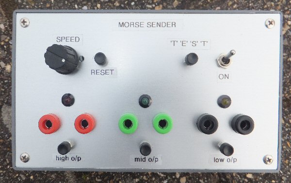
Each o/p also has a button which is used to send a unique number in morse code. The mirror galvanometer users have to read these signals to get the three numbers. This of course gets harder to do as the signal levels become smaller / weaker. Each o/p has an LED to show it is sending data. In the 'TEST' mode you see the LED's flash with the morse code but when they get to decoding the numbers the LEDs simply stay on while sending and dont give any visual clue to the data being sent!

I used a PIC16F84 and programmed it in assembler code to create the signals. 6 output pins of the 8 bit port were used. Two pins are used for each o/p. Normally each of these will be at zero voltage but one will go high so that current flows in different directions for a dot and dash e.g. for a 'dot' the first output (A0) of the port is set to ON, i.e. A0 = 1 while A1 = 0 for a 'dash' A0 = 0 and A1 = 1. When no signal is to be sent A0 = A1 = 0. Each pair go via resistors to the sockets so that the 5V is converted into a current (total of 4k7 to get ca. 1mA, 47k to get ca. 100μA and 470k for ca. 10μA).


Wiki Mirror
galvanometer
more
soon
more
soon
more
soon
PIC page


THE CREATIVE SCIENCE CENTRE


Dr Jonathan Hare, The University of Sussex
Brighton, East Sussex. BN1 9QJ

home | diary | whats on | CSC summary | latest news