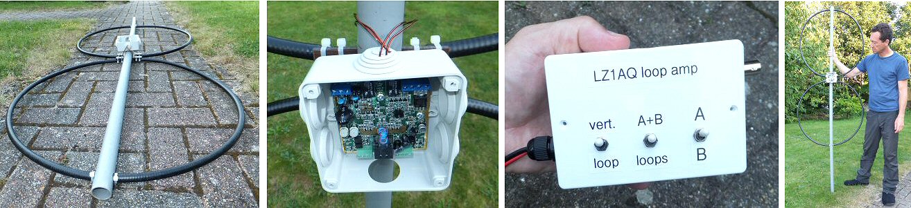
LZ1AQ active loop antenna device

active loop antenna


Many of us are suffering from lots of local noise on the HF and LF bands. This may originate from digital devices such as TV's, LED lighting, solar power arrays and switch mode supplies etc. One way to try and overcome these problems is to use a directional receive antenna to null-out the worst of the noise. I have used loop antennas with great success on 80m however the standard capacitor tuned loop is a very narrow band device. This is very good for minimising the incoming signal strength to the front end of a receiver but it does mean re-tuning the antenna when I move around the band. My particular 80m loop only covers 3.5-4 MHz so it is a one band device. The active loop antenna described here cover from about 30kHz - 50MHz (the exact frequency range depends on the inductance of the loops etc.), has a good null in its reception responce and does not require tuning. I used surplus sections of Andrews coax, using the outer copper tube as the loops. Its better than aluminium as you can solder to the ends and the plastic coax outer protects the copper from weathering.


LZ1AQ URL links

LZ1AQ
Home Page
LZ1AQ active
antenna amplifier
Wideband Active
Small Magnetic
Loop Antenna
back to G1EXG
radio page


LINKS TO PDF's

pre-amp
spec.
pre-amp
description
Antenna
description
Q & A Mounting
Instructions


Some notes using the LZ1AQ active antenna

* this is a receive only antenna - you can't transmit up it!

* Please don't change / modify or extend the FTP cable as it has been made for the job
(it's got a screened plug at the controller-end but a non-screened plug at the antenna)

* The white control unit box needs 12V DC power. Don't use a switch mode power supply as it will inject lots of noise into the receiving set-up.
If in doubt use a 12V battery for lowest noise. I use my Watson transformer 12V radio supply all ok.

* The antenna is water proof and can go outside. The white control unit needs to be inside close to the radio.
Move the antenna around the garden a bit to find the place of lowest noise and of course rotate the loops for a null in the noise.
For initial setting up very long headphone extension lead can be useful to listen for a null in the noise while rotating the antenna outside.

There are three toggle switches on the control box, they switch between:
1) small 'vert' (electric field, see description below) or loop(s) (magnetic field, see description below)
2) A + B or single loops
3) loop A or loop B

Vert mode - When the first switch is put into 'vert' mode the two ends of each loop are shorted together and the two loops form the two arms of a short dipole. In this mode the device predominantly receives the electric field of the radio waves. In 'vert' mode the other two switches do not do anything. If the antenna is mounted vertically in 'vert' mode there is no directivity so there is no advantage rotating the loops.

Loop mode(s) - With the first switch moved to the 'loop' position the device predominantly receives the magnetic field part of the radio wave. When using loops the antenna becomes directional and you can 'null-out' noise or rotate the loops to peak a signal. In loop mode the antenna works well even close to the ground. Changing the second switch allows you to select i) each loop separately (using the third switch with positions A or B) or ii) add the two loops together A+B in, what is effectively a loop of twice the area. A+B is usually better than A or B on their own.

Note: I have mounted the two loops in the same plane but an alternative arrangement could be to mount loop A at 90 degree to loop B. Then you could use the third A / B switch to control the directional characteristics of the antenna (but in this case the A+B setting would now not work properly).

Jonathan Hare, G1EXG, August 2016


THE CREATIVE SCIENCE CENTRE


Dr Jonathan Hare University of Sussex, Brighton.
e-mail: j.p.hare@sussex.ac.uk

home | diary | whats on | CSC summary | latest news