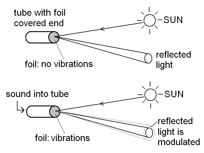
The basic outline of the light beam transmitter. Vibrations on the foil (due to the sound) cause the reflected light to be amplitude modulated.
Note: for details of talks and workshops on this topic click here:
talks and workshops
Click here for details of a mini lightbeam device
Click here for a light beam mini film
Summary
Here we describe a simple process to 'put a voice on a sunbeam' and transmit it over a distance. It is a fascinating example of amplitude modulation of light using sound vibrations. We then describe how the modulated light is detected and demodulated in a receiver so that we can hear the sound. A wide range of physics and engineering experience can be learnt through these exciting 'sunbeam' experiments. These activities are inexpensive and can be made in a school laboratory or at home.
Introduction
The interconnected computers forming the Information Super Highway (the Internet) depend on the ability to encode and decode information (e.g. a voice, picture or program) on the communication network. This network might be thousands of miles of wires, fibre optics, under sea cables or use satellites. Although this 'information' may appear in an identical from on the distant computer there must be a large amount of encoding / decoding along the way, to make it all happen reliably.
The process of encoding information for transmission is called modulation and the subsequent information retrieval is called demodulation. On a computer system a 'black box' does this job at either end of the network and is called a Modem (short for Modulator / Demodulator). With other types of information communication, for example in radio broadcasts, the modulation of the programme is done at the transmitter and the demodulation performed within the radio receiver.
In the following article however, we look at a more simple system which uses a most basic modulation / demodulation process called amplitude modulation. We will learn about this process in an exciting and entertaining way. Bright sunlight (a sunbeam) will be modulated to carry voice information. Then, after sending it over a distance, we will demodulate it to be able to hear the sound.
The experiments described here were one of the challenges for the popular BBC2 / Open University TV series - Rough Science - and the series were first transmitted in the UK in January 2004.

How it works
In these experiments Sunlight strikes an aluminium foil diaphragm (or mirror, see 'transmitter' section below) covering the end of a tube. When you talk into the tube the sound waves travel down causing the foil to vibrate. The light hitting the foil would normally reflect off at an angle. But now additional constantly changing deviations in angle, take place which dependant on the amplitude and frequency of the foil diaphragm vibrations.
At some distance away the reflected spot of light may appear slightly fuzzy instead of sharp because of this 'modulation' movement. If you take a small part of the spot its amplitude will vary over time. It will vary in exactly the same manor as the vibration of the foil due to the voice sound waves. The reflected light beam has therefore been amplitude modulated by the sound.
If we arrange for a light detector to receive some of this modulated light its electrical output will vary (because of the amplitude modulation) in an identical way to that caused by the voice. When this is amplified and fed to a speaker (a transducer that converts electricity to sound) we hear the original sound once more!
In practice you need to arrange the transmitter reflector so that it receives a good source of direct sunlight and of course the receiver needs to be able to clearly see the reflection – but it is really as simple as this!
Sunbeam communicator apparatus
The Transmitter
This is an open tube made from plastic, cardboard or metal having dimensions between 1-10cm diameter and 10-50cm long. One end has a thin layer of aluminium foil taped over it. In practice all sorts of diameters and lengths need to be tried to find the most efficient for your set-up. You might also try other reflecting surfaces for the diaphragm, such as shinny gift wrapping foil, a mirror fixed to a rubber sheet etc.
The receiver
Choice of light detector
The detector does the very important job of converting the light into electricity. The signal then needs to be amplified in order to drive headphones or a speaker (although if the light and modulation is strong enough you can drive headphones directly, see below). A standard solar cell will give good results as a detector. However, it is possible to make your own detector and this was the Rough Science solution as we were not given a solar cell. We used a modified transistor (see below) as a detector.
A typical transistor has an area of less than 1mm² while solar cell are easily obtained having dimensions 50 x 50 mm which will in principle detect over 2000 times more light! Obviously the solar cell will allow for far greater distances to be covered by the experiments but it does not have the magic of the make-your-own approach (we will see below there are ways of improving the home made approach however).
The transistor detector
The transistor is a device that amplifies small electrical currents into larger copies (see the article mentioned in the reference section below to see how the transistor works). Transistors are made from semiconductor materials that are intrinsically light sensitive. In other words their electrical properties are affected by light. For these and basic mechanical reasons transistors are encapsulated in plastic or fitted inside metal cans.

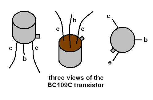
Metal transistors are commonly available and used extensively in consumer electronics. If the top of the metal can is carefully filled away then the tiny transistor can be exposed. This is a small square of silicon having dimensions about 0.5 x 0.5mm with tiny wires that connect it to the wires outside. The exposed transistor can then be used as a simple light detector.
If light is shone onto the transistor one finds that a small current is produced. Solar cells are silicon diodes. Transistor can be considered as being composed of two diodes with a common connection. When light falls on the modified transistor we are making use of the transistor diodes and actually we have made a tiny solar cell from the transistor. The transistor has three connections called the base, collector and emitter. The base is the common connection between the two diodes and so a light-generated-current can be obtained by wiring to the base and one of the other connections. In practice you might find that any two connections will work, but you may find there will be a single pair that will work more best.
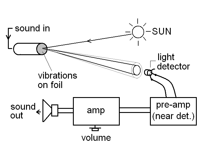
The electrical signal from the detector will consist of an alternating (AC) voltage from voice modulation superimposed upon a constant voltage (DC) produced by the basic ambient light (in practice the modulation of the light is only slight). As all the information is in the AC part of the signal we can ignore the DC part (which would limit how much we could amplify the signal as it would saturate the amplifier). As capacitors only pass AC signals one is used in the circuit to block the DC signal and only let our precious modulated signal through to the amplifier. As the signal is AC it also means we don't have to worry about which way round we connect the detector to the amplifier.
The simplest receiver
If the reflected light is particularly bright, or you just want to test that the transmitter is working when being very near to it, then there is a wonderfully simple solution to the receiver problem. You can use a solar cell connected directly to a pair of headphones! This simple solar receiver only needs the sunlight to work. Of course the range is very limited. As the solar cell provides a relatively low voltage but fairly high current this receiver will work well with standard low impedance headphones (8-16 ohm) such as found on stereo systems and portable cd / cassette players. Only use this set-up with reflected sunlight as the direct sunlight current might damage the headphones. There will not be enough power to drive a loudspeaker.
The pre-amplifier
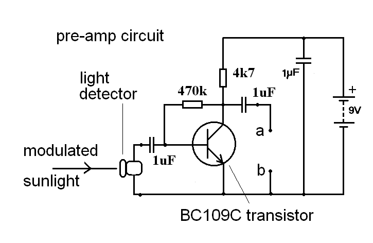
To get a good distance you will need to amplify the detected signal. Although you can send the signal from the light detector directly to a standard audio amplifier the sensitivity (range) can be considerably boosted if a pre-amp is used. A very simple 1 transistor amplifier is shown below in the diagram and is capable of producing about 100 times amplification. You can use the same type of transistor for the pre-amp as you did for the detector (see parts list below).
For stability it needs to be powered from its own 9V battery. To minimise noise pick-up the pre-amp should be wired as close to the detector as possible. Current consumption is low and it should work for many hours on a new battery. Remember to turn it off when not in use.
The main amplifier
The amplifier can be a pair of computer or personal stereo speakers but note that they must contain an amplifier (and be battery powered). In the rough Science series I used an old portable stereo and wired the pre-amp output into the amplifier via its volume control.
The circuit of a simple integrated circuit amplifier is shown in the diagram. This will work well on a 9V PP3 battery. A pair of twisted wires or coax should be used to connect the pre-amp to the amplifier (via connections a and b, see diagrams).
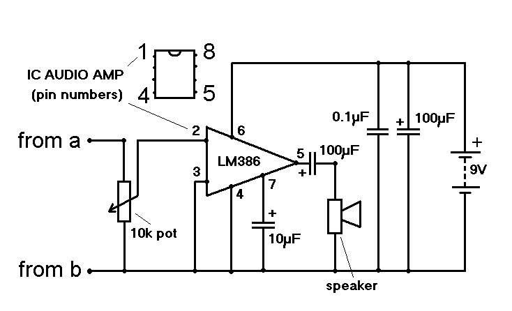
Ideally both the pre-map and the amplifier should be constructed on strip-board but it is possible to simply solder the components together in a 'birds nest' type of construction, taking care to make sure that no wires do not short circuit.
Component values
None of the electrical components values in the circuits are very critical. For example a 4.7 k volume control will work instead of the 10k shown and any value of capacitor between 47 to 220uF in the speaker circuit will work. Using some other value other than 470k on the pre-amp circuit (ie. 100k to 1M ohm) will change the gain slightly.
Getting it all to work - setting up
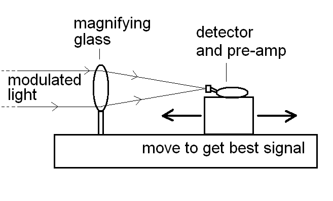
Depending on the position of the Sun and the receiver you will need to experiment with the orientation of the foil diaphragm. The Sun moves through the sky over the day and so you will have to re-adjust regularly. A large board painted black and fixed behind the receiver helps in setting-up as one can see the reflected spot of light more easily. Finally when the spot of light falls on the receiver either 1) adjust the solar cell to pick up as much of the light as possible or 2) adjust the magnifying glass to give a sharp spot of light on the transistor. In the later case you might find that best signal does not occur when you have the sharpest focus.
Finally some spy tricks!
The theory described here can be useful for spies and other clandestine operations! It is possible that sunlight or laser light reflected off a window pane can become modulated with the voices inside the room (because the sound in the room will vibrate the window slightly). If the spy initially sets-up with a visible laser to check the apparatus is working but then switches to an infra red laser, no one will be able see anything going on. If one demodulates the reflected light one can then eavesdrop on the people!
Further experiments to try
1) To get a system that can reliably transmit 100m or so using a solar cell detector is quite easy but you will need to experiment some what if you use the modified transistor as a detector. Try a number of different tube transmitter designs, shape and sizes as well as different reflecting diaphragms - play around with foils of different stiffness, reflectivity and try gluing small mirrors on to a rubber diaphragm etc.
2) Try to cut out stray light to the detector as this will improve the performance considerably as it will reduce the noise. A cardboard hood, or some other device, around detector is therefore a good idea.
3) The magnifying glass in front of the transistor detector improves the performance of the set-up considerably. In conjunction with the hood (see 2) above) it may also help to cut out stay light from other sources (i.e. directly from the Sun) and reduce the overall noise level. When transmitting over greater distances one could also consider making up large aluminium foil parabolic reflectors to capture more light than the lens.
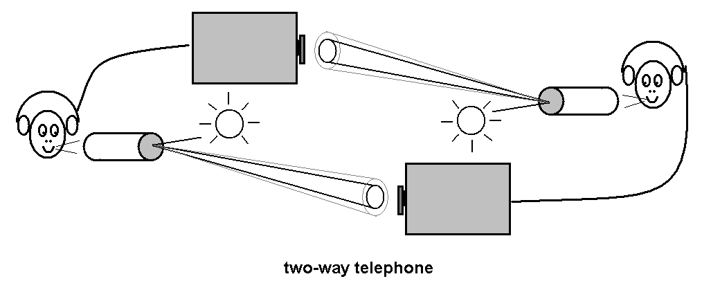
4) A two way communication system could be arranged but the two stations would need to be carefully placed for both to get a good source of light. One could imagine that the noon day solution where the two stations could be placed either side of a North-South line, one to the East and the other to the west of the Sun.
5) Try using more than one transistor in the detector. An array may improve your chances of a steady signal and make alignment easer but some experimentation will need to be made. Large power transistors (such as a 2N3055) should have a much larger internal transistor surface area than the small BC109's. They are also easy to find on old circuit boards from old surplus power supplies etc. However the top of the can seems to be fixed in some way to the internal connections and on removal you might find that you damage the silicon.
References and web sites:
1) For details of light beam transmitters and also a short history since Edison's first experiments see the wonderful notebooks - The Forrest Mims Circuit Scrapbook, Vol. II, LLH Tech. Pub, 2000, ISBN 1 878707 49 3
2) To know more about the way the transistor works see – The wonderful amplifying action of a Transistor, J. P. Hare, Journal of Physics Education, spring 2004, Institute of Physics Press.
3) The Open University Rough Science web site: www.open2.net/roughscience4.html
4) The Creative Science Centre web site: www.creative-science.org.uk
Parts List:
Semiconductors:
1 x Detector Transistors: BC109C (almost any NPN metal can transistor will work)
1 x Pre-amp transistor: BC019C (C means high gain)
1 x LM386 audio amplifier IC
1 x solar cell (say 3cm x 1cm area or larger)
Resistors: 1 x 4k7, 1 x 470k
Capacitors: 1 x 0.1uF, 3 x 1uF, 2 x 10uF, 2 x 100uF
Variable resistors: 10k log potentiometer for amplifier volume control
Other parts / components:
1 x 8 ohm speaker (any size)
1 x Standard personal stereo headphones (8-16 ohms)
5m of twisted cable
5m of audio coax cable
2 x 9V PP3 batteries and snap on connectors
1 x magnifying glass
Various pieces of wood to make up tripods and apparatus to hold magnifying glass and detector as well as hold transmitter tube etc.
Acknowledgments
I would like to thank The Open University, BBC and all the Rough Science crews, Rough Scientists, directors (Jonathan Renouf et al.), camera and sound men. Also thanks to Forest Mims for his inspirational notebooks (see references section above). Finally I would like to thank NESTA (National Endowment for Science, Technology and the Arts) for support.
Additional Notes
[1] The eye does not respond fast enough to actually see the changes in amplitude due to the modulation. Consequently the modulated spot will simply look 'fuzzy' compared to that produced by a normal reflection.
[2] An interesting observation is that a thin beam from a laser does not work as well as sunlight. Apart from the fact that there is a great deal more energy in a sunbeam I think this might be due to the fact that the foil diaphragm is resonant at different frequencies (and possibly amplitudes) at different places on the surface. So when a wide light sunbeam hits the surface all these resonances are passed on to the reflected beam. When using a laser pointer however only one part of the foil reflects and so the reflected beam passes on only a highly distorted part of the modulation spectrum. The result is a very tinny and distorted sounding transmission.
[3] If you want to experiment in-doors then you will have to use a powerful torch as a light source – not mains powered lighting. The reason is due to the 50 Hz AC alternating power. The lights themselves are therefore slightly modulated at 100 Hz (100 because the bulb will light irrespective of the polarity of the power). If you use mains powered lighting you will hear a loud hum noise above the voice signal.
[4] The description given here of the amplitude modulation produced by the vibrating diaphragm is a simplified account. It is possible that the complex vibration and standing waves on the foil diaphragm surface scatter light away in such a manor that the light beam moves very little in angle but still changes in amplitude at the distant spot quite considerably. In this way it might well produce amplitude modulation without much angle deviation. This makes some sense otherwise one would expect the relative modulation to increase as one gets further away from the transmitter (cf. moving spot light galvanometer).
[5] The very simple receiver described above (connecting a solar cell to standard headphones) is fun to explore the modern technological world with. It almost gives you another sense to play with (actually it extends the frequency response of you eyes by using your ears). Try putting the receivers cell near to the light from a computer monitor or to a TV screen. The moving dot that makes up the TV picture, modulates the light and can be heard in the headphones. Try also looking at/ hearing the modulation on LED's alarm clock displays, fruit machines etc. The use of pulse width modulation to vary bulb brightness in these devices can be 'heard'.
[6] The simple pre-amp described above enables you to get started with these interesting experiments. More gain is handy and can be provided quite easily by using a transistor Darlington pair instead of the single pre-amp transistor. Here the base, collector and emitter of the single transistor is swapped pin-for-pin with the base common-collector and emitter of a Darlington pair. If this is done the 470k ohm resistor in the original pre-amp circuit must be changed to 10M ohm. See J. P. Hare, J. Phys. Ed. March 2004, p128-131 for details of the Darlington pair.
[7] Also see these great sites for LED light beam communications:
Luxeon LED
OPTICAL COMMUNICATION FOR THE AMATEUR
Please note that this article has been published in Physics Education
see J. P. Hare, IOP press,
Journal of Physics Education, May 2004, p.242-246
JPH Jan 2004
home | diary | whats on | CSC summary | latest news