An 'Inverted-V' antenna for the main HF bands

NOTE: I am still working on this page, so sorry about the spelling, english and the science !


Described is a simple inverted-V antenna which, when used with a balanced ATU, can be used on all the main Radio Amateur HF bands (80, 40, 20, 15 and 10m). The cental support is made in such a way that the wire can be coiled up for storage when the antenna is taken down.


portable antennas


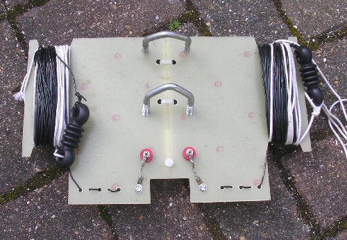
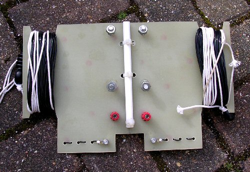
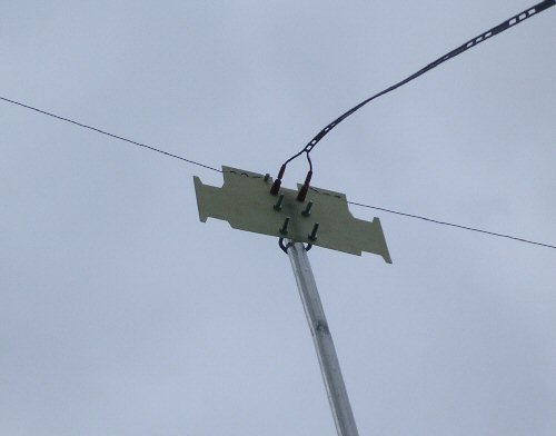
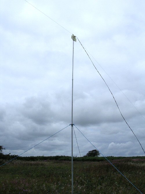
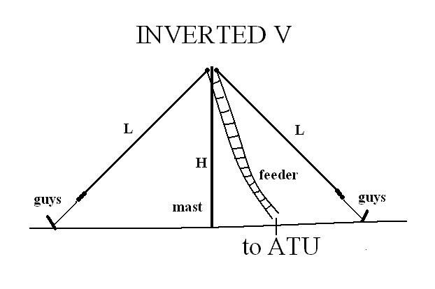
The basic inverted V antenna. Each side length L is a quarter wavelength for the lowest frequency so L=20m (65'). For an ideal apex angle of 90 degrees the mast height H would be over 14m. Lower mast heights will work but the antenna may not be omnidirectional (e.g. more like a dipole).


The basic inverted V antenna. For an all-band antenna (from 80m to 10m) each side length L should be a quarter wavelength for the lowest frequency which for the 80m band give L=20m (65'). For an ideal apex angle of 90 degrees the mast height H would be over 14m. This is quite a large mast to take along for portable work and so lower mast heights can be used but the antenna will behave more like a low dipole rather than the omnidirectional inverted V.

Feeding and tunning
Any length of open wire (300-600 ohm) feeder can be used but if you use 20m (65') then it will be roughly resonant for the higher bands which may help tuning. A balanced ATU is required to match to the radio. As the AR bands are harmonicaly related the antenna has progresively higher gain as we go up in frequency although with a more complex radiation pattern.

Construction
I used a piece of fibreglass pcb to act as the central insulator and this was also used as a wire bobbin for the two arms so that the wire can be easily stored when taken down / put away.


portable antennas


portable antennas


The whole antenna then is neatly packed up when not being used and easily packed away in a ruck sack without worrying about the wire forming a birds nests in transit, or unpacking! The central former also has two U-bolts for fixing to a mast and also a plastic tube which can be used to slip over the narrow end of a fibre mast. Finally banana sockets connect the two inverted V wires so that the feeder can be attached.


portable antennas


Balanced ATU
You can feed the inverted-V directly with 50 ohm coax like a dipole. This will only really work for oporation on one band only (in this case 80m). It's not a good option as the length L will have to be pruned for low SWR and this will change each time you change location, mast height etc. which for portable oporation is not practical. A balanced ATU has the advantage of bringing the whole system to resonace, act as a band pass filter (both on receive and transmit) and always quarantees a low SWR.

click here for details of a balanced ATU


SETTING-UP
Below shows the inverted V on a metal mast up at about 6m above ground level. I also tried out the inverted V with a '10m' fibre mast. The top sections are so thin thay are not very useful and so were removed to make an 8m mast. The plastic tube on the central panel was slotted into the top of the mast and the whole thing was erected. Three guys held the mast in position while the two antenna arms slopped towards ground. The end insulators then were connected to about 20' of insulated guy rope and pegged into the ground. This way the V arms slopped toward ground but did not touch the earth. With such low mast heights the apex angle will be much greater than 90 degrees and so the antenna will work more like a low dipole.

portable antennas


RESULTS
Using just 5W from an FT817 I've worked all round Europe on 40 and 20m (eg. HF60PW and LZ2JA was at 1500km) with this antenna, ive not had such good luck beating the pile ups on nice DX such as JA's and W's on 20 and 15m though !

Some thoughts about the 80m band

back to G1EXG's Radio page


THE CREATIVE SCIENCE CENTRE

Dr Jonathan Hare, Brighton, East Sussex. BN1 9QJ.

home | diary | whats on | CSC summary | latest news