Summary - A laboratory instrumentation amplifier is described that can measure μV DC voltages which will be useful for a range of interesting physics and engineering experiments (e.g. Hall effect, potentials, photo current effects etc.). The 'flying capacitor' (switched capacitor) input stage provides a true differential input, minimising input offsets and earth loops, that can cause errors when measuring small signals. etc. The electronics is made from easily obtained components and can be constructed fairly cheaply.
Tests & experiments that can be used to test the amplifier out, as well as some details about investigating the Hall effect with copper foils can be found here:
To me science is about making and measuring things, and electronics provides a wonderfully creative (and economical) way of exploring science through the process of designing and building scientific instruments.
The problem-solving you need to overcome building, testing and calibrating the experiment will also force you to confront your immediate assumptions and preconceived ideas - which is often a good thing. In trying to understand nature, you keep learning. Building scientific instruments (even simple ones) makes you feel like you are discovering the world all over again, as if these devices equip you with an extra sense of the world.
Described here is a 'flying capacitor chopper stabilised' (FCCS) amplifier (based on an 'instrumentation switched capacitor building bloc' (more info. below) that will be useful for all sorts of interesting scientific and electronic engineering experiments where you need to measure small DC (or very low frequency AC) voltages.
It's a few years since this circuit was 'state-of-the-art', but I chose this deliberately as it means the integrated circuits are easy to track down and can be brought quite cheaply (e.g. Ebay). The single most expensive component in my design is the painted metal box, but of course you don't need to use this! (although a screened metal box of some kind is essential).
Standard op-amp circuit
It's quite easy to make high gain AC amplifiers from integrated circuit op-amp circuits and a typical hi-fi or radio make use of many of them. This is because in AC amplifiers, signals are often coupled from one stage to the next by capacitors. These block small offsets and drifting voltages which can be a problem in multi-stage DC amplifier circuits, as these rogue signals can get multiplied up (although even in AC amplifier these can cause saturation problems including signal distortion etc.).
DC amplifiers with x 10 and x 100 gain (i.e. that will multiply a signal 10 or 100 times) are fairly easily created at low cost using op-amps. These can amplify signals down to a fraction of a mill-volt and perhaps smaller signals if you are careful about the design and circuit layout. Improvements can also be made by using differential input circuitry, where a lot of the noise pick-up can be cancelled (common mode noise). However, making a stable high gain DC amplifier, to amplify small µV signals, is much harder.
Here are a few problems you face when trying to make high gain sensitive DC amplifiers:
* output variations due to thermal drifts (in the experiment and the electronics that measure them both slow and fast)
* amplifier input / output offset currents and voltages
* 50 Hz (and 60Hz) mains pick-up (e.g. 'hum loops')
* unexpected voltages created across the input leads themselves
* contact potentials between the components and solder joints etc.
If you want to measure small DC signals (possibly in electrically noisy environments) then we need to explore other techniques than basic op-amp circuits - hence the reason for this project.
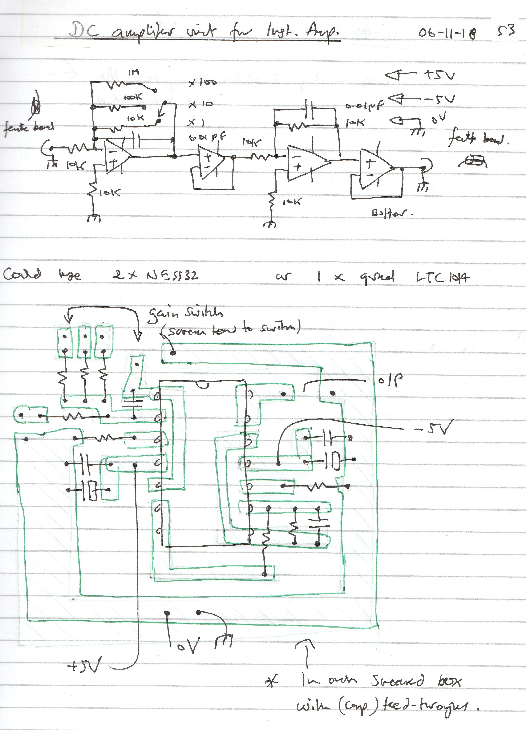
In this project we use three stages:
1) switched (flying) capacitor input
2) a chopper stabilised amplifier (x 1000 gain)
3) extra gain block (provides x1, x10 & x100 gain)
click here for circuit diagram of amplifier
1. Instrumentation Switched Capacitor Building Bloc - using a 'flying' or switched capacitor
One way of removing, or at least reducing, some of the problems of rogue signals when we make a measurement, is to make sure we don't directly connect our experiment to the amplifier at all!
You can do this with a circuit that alternately switches a small capacitor across the signal you want to measure and then shares it - now charged up with a snapshot of the signal - with a similar capacitor on the input of the DC amplifier. The 'flying capacitor' or switched capacitor creates an almost ideal differential input stage for a DC amplifier, as the amplifier is never directly wired to the signal source.
An integrated circuit called a LTC1043 is an 'Instrumentation Switched Capacitor Building Bloc' that has all the switching internally sorted-out, you just need to add a few other components (the capacitors in particular). The data sheet provides more details [2].
see data sheet here:
click here for LTC1043 data sheet
Note: this technique can't be used at frequencies higher than about half the capacitor switching frequency, otherwise aliasing (signal beating) problems are created. So, it's only useful for relatively low frequency AC or DC only measurements (see data sheet).
2. Chopper stabilisation
In addition to the switched capacitor input stage, we also include a chopper stabilise amplifier to get maximum performance [3]. As mentioned above, measuring small DC voltages is problematic due to the far from 'ideal' performance of a typical amplifier. Input-offset currents and voltages are created by the internal (inside chip) amplifier circuitry that can lead to distortion and changes in amplifier response. These can occur due to room temperature fluctuations and heating caused by internal circuit currents.
A 'chopper stabilised' amplifier tries to overcome many of these internal problems by using a built-in oscillator arrangement that alternately switches circuit structure to cancel these off-sets and drifts. It creates an amplifier with very low drift (typically less than 0.05 μV / C) and low offset (typically less than 5 μV) on the output. From the point of view of the user the chopper stabilised amplifier looks just like a good amplifier, and the internal switching should be invisible from the outside (but see note below and data sheet for more info.). Here we use a LTC1052 chopper stabilised op-amp, see data sheet [3].
Note: again, the internal switching of this second stage, means you can't use the chopper stabilised amplifier at frequencies higher than about half the chopping frequency, otherwise aliasing (signal beating) problems are created. So again, it's ideal only for relatively low frequency measurements (see data sheet [3]).
There are therefore two different chopping / switching frequencies we need to be aware of. In principle with good circuit design, and proper application of the amplifier in our experiments, these should be 'invisible'.
Bringing the two together
The combination of a 'flying capacitor' input circuit and 'chopper stabilised' amplifier creates a very sensitive, stable and drift-free low frequency amplifier. The flying capacitor input stage does not provide any gain or loss (i.e. will have gain of x 1), once the circuit has settled down. The chopper stabilised amplifier in this resistor configuration provides a gain of x 1000. The two units together, the flying cap IC and the chopper stabilised amplifier will therefore give a gain of x 1000 times. I used the circuit example on page 10 of the data sheet ('Ultra Precision Instrumentation Amplifier' for the LTC1043 IC [2]) but I removed the part of the circuit that generated the small negative power supply voltage. Instead, I use a separate + and - regulated power supply, so both + and – input signals can be measured.
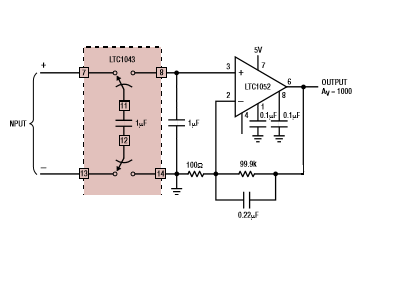
Here I have used the circuit example on page 10 of the data sheet ('Ultra Precision Instrumentation Amplifier' for the LTC1043 IC) but removed the part of the circuit that generated the small -ve voltage (from the positive) as I use a separate + and - regulated power supply so full (equivalent) + and - input volages can be measured.
3. Extra gain block (x 1, x 10, x 100)
In my prototype I have also added an extra block of op-amp circuits after the x1000 FCCS circuit. There are three gain selections (via a front panel rotary switch): x 1 (i.e. no extra gain), x 10 and x 100. Along with the x1000 gain of the FCCS, this will give total amplifier gains of x1000, x10,000, x100,000.
Note: standard op-amps are fine to use in this extra gain block, as the signals are now much larger, although they will add a bit more noise on the output. I used a low noise quad op-amp (LT1014CN) to create this extra gain block which provides two inverting amplifiers (so non-inverting amplification overall) and provide buffering for the output so that the metering / logging circuitry will not load the amplifier (within reason of course).
You could just use the first two op-amps (i.e. o/p III, although the o/p will be inverted) in this circuit. I added the last two op-amps to form an averaging circuit to reduce noise. The 10k on the third op-amp has a 0.01 µF capacitor (CT) across it, that acts a low pass filter. You could increase this capacitor to say a 10μF (unpolarised) to reduce noise still further (ca. 0.1 second time constant).
As the first (FCCS) stage provides so much gain (x 1000), it may well be that the x 10 and x 100 range of this extra gain bloc will never be needed but this will of course depend on the particular experiment the amplifier is going to be used with and the type of voltage recorder / logger that might be used.
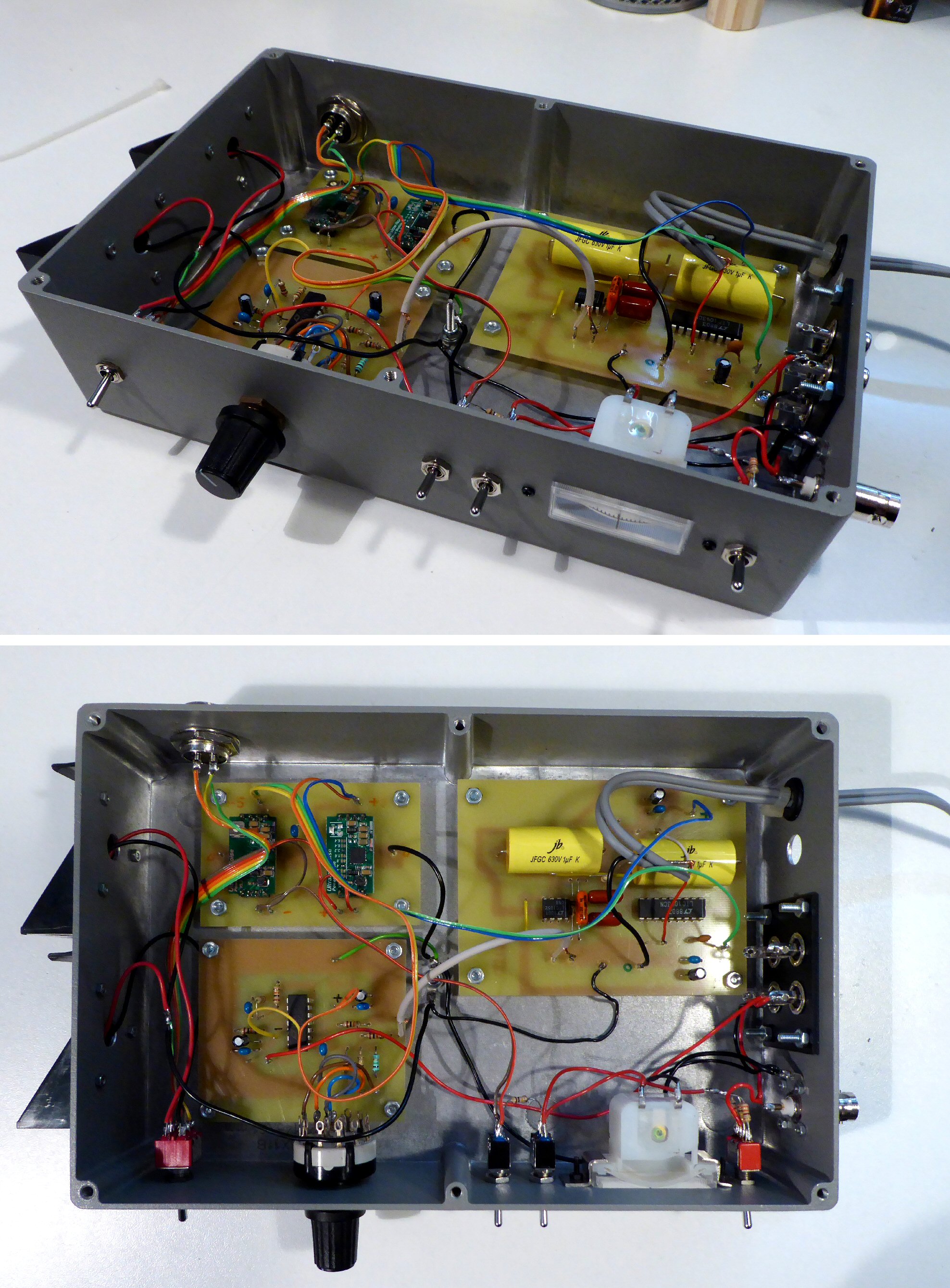
I built the first stage (FCCS) amplifier and the extra gain block, and low noise power supply units (more details below) on different circuit boards and mounted them in a metal (screened) box. All the 0V (earth) connections go to a single common point toward the center of the box (to reduce hum-loops etc.), see photos.
Battery and regulated supply
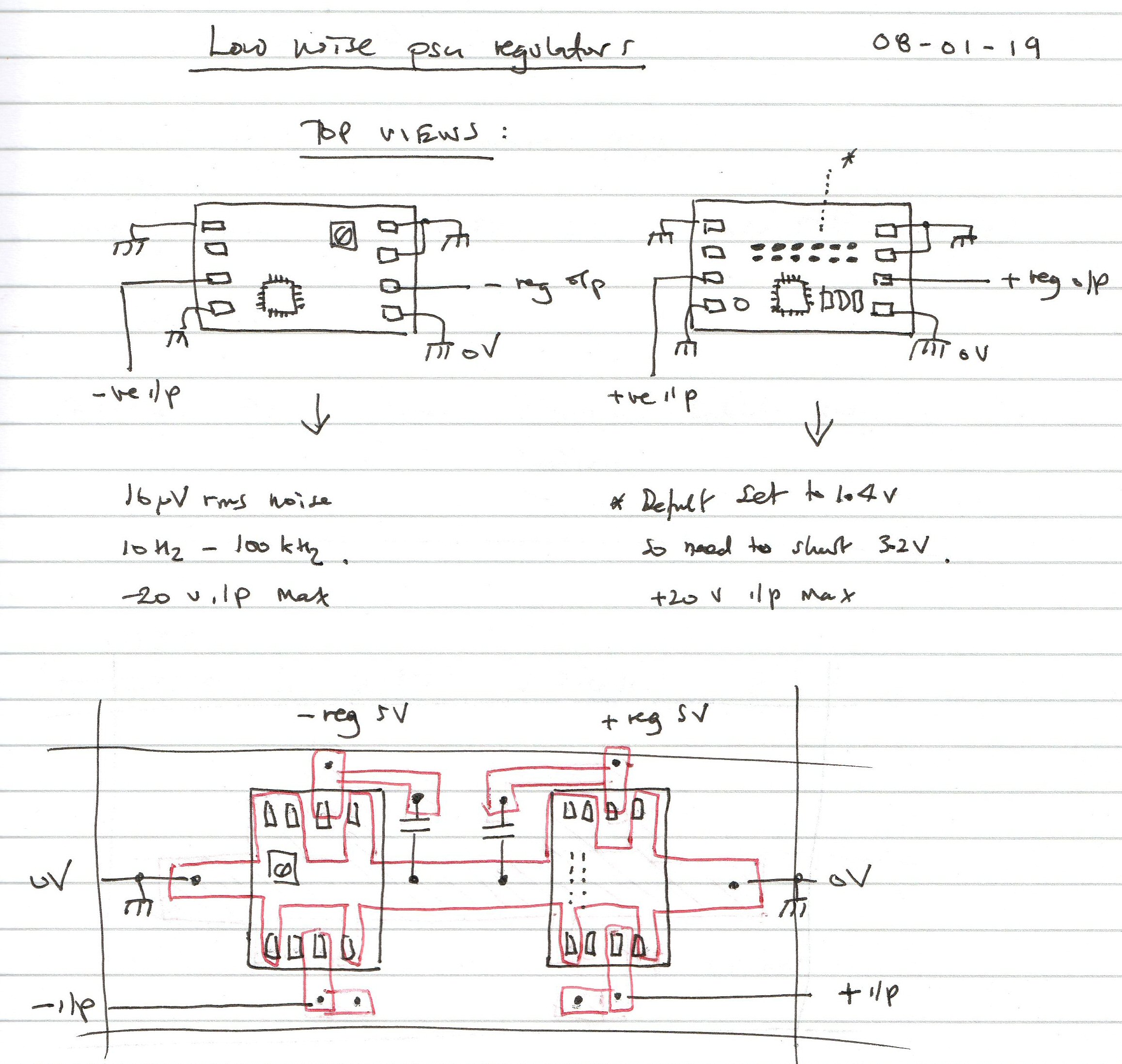
Both the flying capacitor and the chopper stabilised amplifier stages need a ±5V supply. You can of course use a mains powered power supply, but as I wanted the amplifier to be portable, I decided to use low noise regulator power supply boards. These are used both when using batteries (2 x PP3 9V) or on an external power supply.
The positive regulator board is based on the TPS7A4700 Low Noise low drop out (LDO) IC (set for +5V, see below). The negative regulator board based on the TPS7A3301 Low Noise LDO IC (set for -5V, see below). These small pcbs can only supply a few 100mA but are ideal for our amplifier as they do not take much current. The units have solder pads to program the regulation voltage. The default (i.e. no-pad soldered) is 3V so you can't over volt by accident.
I am not sure these very low noise regulators are actually needed in this circuit, but as we are going to measure very small voltages, it does make sense to make sure the power supply is as low-noise as possible. The units were quite low priced and were fun to set-up and use (and being a positive experience, I will probably use them again in other projects).
Battery holders on outside
You will notice on my prototype that I put the batteries on the outside of the case. I often find that the batteries in instruments that might only be used intermittently, can end up leaking and these liquids and vapours tend to rot the electronics. As a result, I have started to mount the batteries on the outside of a lot of my homemade test gear, partly to remind me to remove the batteries when the device is not used for a while, and partly for ease of replacement. It's not the neatest way of doing things but I think is ok on practical laboratory gear.
Input cable
The input cable should be a high-quality coax cable (twin screened or two single screened cables). In the past I have found coax leads can create small voltages when vibrated or moved about. You should be aware of this 'microphonic' effect when using very sensitive amplifiers. Most plastics are slightly piezoelectric, which means they generate electric fields when moved. This can usually be reduced to near zero by correct matching / loading at the end of the cable. My first prototype used twin screened audio cable, but some experimentation is needed to find what works best in practice.
Sockets
The amplifier output is available both on a standard BNC and one of the phono sockets at the right-hand side of the enclosure. Another of the phono sockets could also provide access to the output of the chopper stabilised amplifier before of the extra gain block (which might provide a lower noise o/p if no extra gain is needed) i.e. o/p I on the circuit diagram.
Capacitors
As the 1μF capacitors are actually the 'signal measuring devices' in the flying capacitor stage of the circuit, we need to use good quality types. I used a high voltage cap as I thought that if the insulation was good to high voltage, it would be low loss in this application. I used 1μF 630V axial metallised polypropylene film capacitor. The chopper stabilised amplifier data sheet also suggests high quality components should be used for the two oscillator capacitors on the LTC1052, I used 0.1μF 100V metallised polyester film.
Front panel meter
I used a small center-zero meter (100μA FSD + range setting resistors) so it can show + and - signals on the output of the amplifier. It is only used as a guide and ideally a digital meter or data logger will be connected to the amplifier output for more accurate measurements / recordings during the experiments. I wired two silicon diodes (e.g. 2 x 1N4148) back to back across the meter which will usually have less than 0.6V across them so will be in a non-conducting state, however if the o/p goes too high at any point, the diodes will conduct and protect the meter from large signal full-scale deflection 'pinging' (i.e. very large full-scale deflection signals). Instead of using an 'ON' led to show when the power is turned on, I fitted a couple of white leds into the back of the meter, so it lights up brightly when turned on - it looks nice.
Ferrite beads
I added a small ferrite bead (ca. with two or three turns of thin enamelled wire threaded through which is a low value inductor) on the input to the extra gain block and on the two o/ps. These are not essential but, in the past, I have sometimes found them useful to reduce oscillation and instability on the high gain settings.
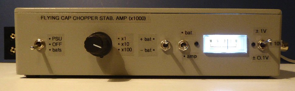
Front panel layout of my prototype, from left to right:
ON / OFF switch: center off, up ON PSU, down ON batteries
three-way switch: x 1, x 10, x 100 gain select
battery test switch: up + battery, down - battery
meter select switch: up battery, down amplifier output
100μA meter (+ LED light)
meter range switch: up ±1V, middle ±10V, down ±0.1V FSD
right hand side connections:
BNC DC output, four phono sockets: so far only one DC o/p
Twin screened coax cable input ca. 1m long
left hand side: 2 x PP3 9V battery and holders
rear: 4 way connector (only 3 cons. used) for external power supply (+, - and 0V)
Notes on using the amplifier
The amplifier chips are powered with +,- 5V so none of the amplifier outputs should be allowed to go beyond 3-4V (or so) otherwise the amplifier outputs may saturate (become a constant voltage near to the supply rail voltage). In the 4 op-amp chain in the 'extra' gain bloc for example you have to be careful that the first op-amp has not gone out of range (i.e. near to one of the supply rails) as its output will then be saturated and will not respond properly. This amplifier won't then pass on a reliable signal to the next stage of the chain. If you can, it's probably best to try and arrange the experiment so that none of the op-amp outputs are above about 1V. That way variations in signal will keep 'within range' and won't go too high, but you also don't want to have too small a signal, so it gets masked in noise. It might therefore be a bit of a balancing act at first to find the best gain setting for a particular experiment.
If you short the input the amplifier output slowly tends to zero. Any residual offset there may be once the amplifier has settled down may be due to small contact potentials from dissimilar metals and solder joints etc. in the input lead and connections. These can be of the order of 1-10 μV. In some experiments we may not be able to remove these and they will appear on the output. As a few μV x 1000 = few mV to 10's mV we need to be aware of these sort of 'offset' signals in our experiments when using such a high gain amplifier.
I found if the input is left open circuit, the voltage slowly ramps up. I guess any small input offset currents on the input of the LTC1052 chopper stabilised op-amp (which although internally cancelled but may still have real offsets on the input stage) will charge up the capacitor(s) causing a voltage ramp on the output. You won't usually notice this, but if you are going to use the amplifier on very high impedance circuits you may need to be aware of this.
Calibration
As stated above the formulas for the gain of the chopper stabilised amplifier implies that you should use 100R and 99.9 k ohm resistors in the feedback circuit, if you want x 1000 gain. I used standard preferred value 100R and 100k resistors because I will use the simple tests below (e.g. test 1) to calibrate the amplifier. Good quality resistors i.e. low temperature variation types may be more important than an exact value. Exact resistor values can be chosen from a batch / made-up from a number of resistors in series, if you have access to an accurate ohm meter.
Note on e-bay components
Electronic components available on eBay are usually good quality and may be the only option available for the rarer types. However, be aware that some components are 'clones' and some may be out-of-spec second rate components. Sometimes you simply have to use what you can get and try them out. As none of the components are very expensive in this project, I don't think you can go too far wrong on eBay.
click here for tests & experiments
click below for higher resolution images:
circuit diagram of amplifier
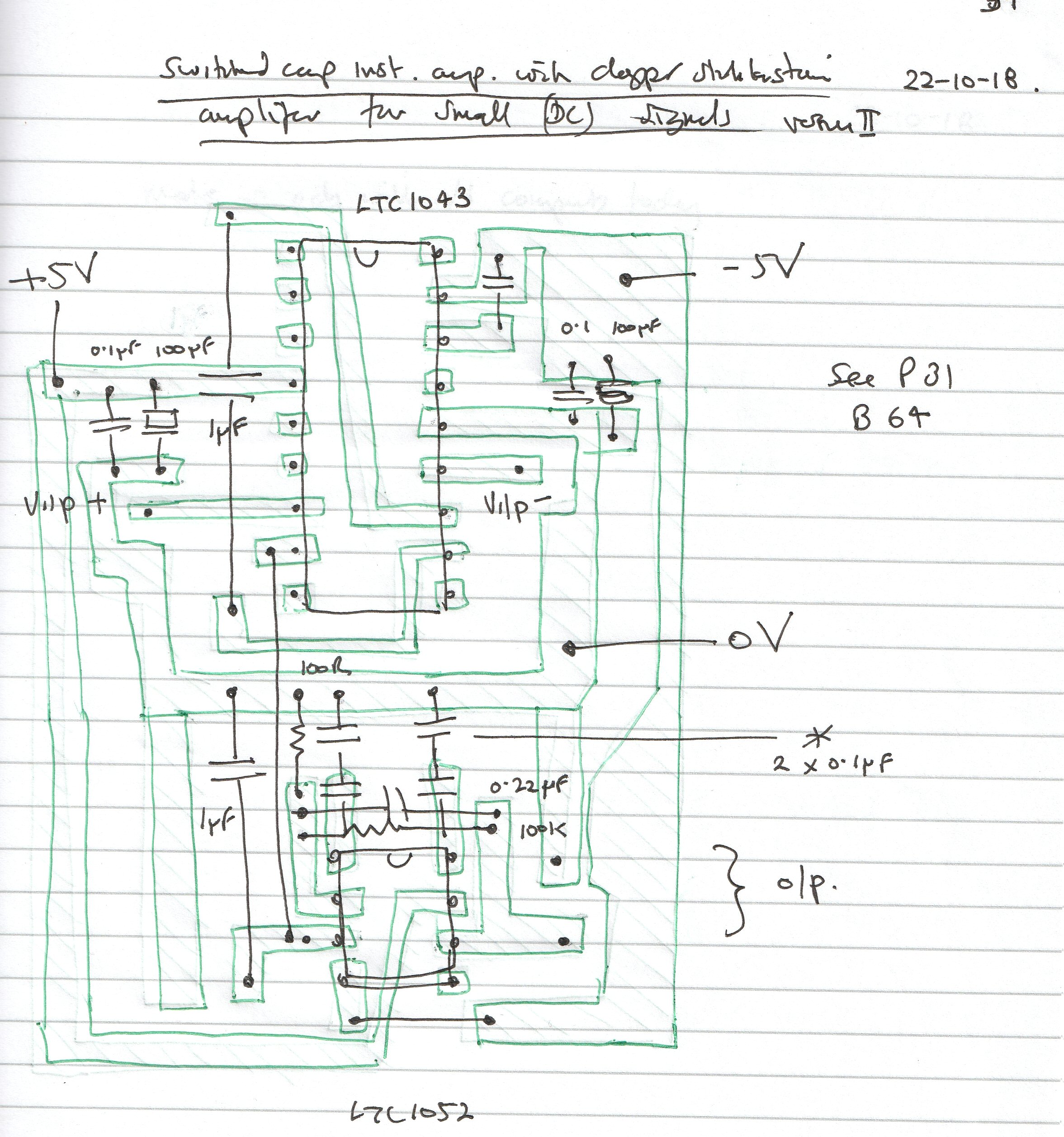
notebook diagrams of fccs unit
notebook diagrams of extra gain block
low noise power supplies
photos of equipment
THE CREATIVE SCIENCE CENTRE
home | diary | whats on | CSC summary | latest news