BACK TO G1EXG RADIO PAGE
EPAD MOSFET - 'near zero' and 'zero' threshold devices
(e.g. the ALD110900)
I will add more details to this page later on but for the moment it gives links to important and inspiring sites.
ARTICLES
1) High Sensitivity Crystal sets, Technical Topics, Pat Hawker, Rad Com, p. 77-78, May 2007.
2) A novel kind of 'crystal set' radio, Giles Read, Rad Com, p. 60-61, June 2007.
3) also see Pat Hawker, Technical Topics, Rad. Com. January 200, page 53-57.
4) High Sensitivity Crystal Set by By Bob Culter (N7FKI)
5) Next-generation Zero-Threshold Voltage EPAD™ design enables circuits with greater operating range in low voltage supply environments
LINKS ABOUT THE CHIPS / DEVICES
1) Advanced Linear Devices web site
2) EPAD MOSFET (ALD web site)
3) ALD110800 and ALD110900 page (ALD web site)
4) ALD110802 and ALD110802 page (ALD web site)
ORDERING THE CHIPS / DEVICES
1) mouser.com (USA)
'CRYSTAL SET' RADIO'S - DIFFERENT DETECTORS
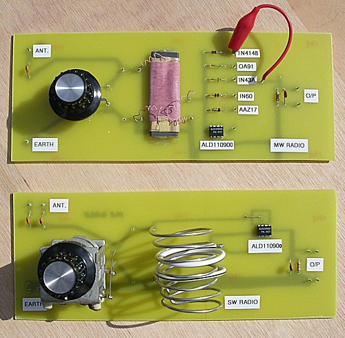
Top: the medium wave (MW) test radio with a selection of 'detectors' (selected by the croc clip lead)
Bottom: the short wave (SW) version with a ALD110900 detector
(on each circuit board the connections are: antenna - top left, Earth - bottom left, audio output (heaphones / amp) - far right.)
RADIO AND RADIO WAVES
The simplest 'radio' can be a piece of wire attached to the input of an amplifier. Why does this pick up radio signals? Well in principle it should not be able to pick up anything but in reality poor solder joints in the amplifier circuitry, as well as point contact effects between the ends of the anenna wire going into the input socket of the amp as well as other effects mean that you do often hear radio signals.
Radio waves are electromagnetic waves as they pass through a metal they induce small voltages into it. Any piece of metal e.g. metal fram specs, tape measures, metal window frames, a piece of wire etc. will act as an antenna and have tiny voltages induced into them. These voltages will be due to natural radio waves (from Space as well as the Sun and Earth), radio stations, satellites, mobile phones, garage door remote controls, microwave ovens .... the list goes on and on.
In the case of long, medium and short wave radio stations the amplitude of the radio wave signal is modified by the music, voice or program - we call it Amplitude modulation AM. Here the strength of the radio waves varies as the tones, loudness and pitch of the program vary. As a result the voltages induced in the metal object antennas distant from the radio wave stations also vary in accord this program information or modulation.
To actually hear the programs on the radio waves you cant actually take this tiny signal and listen to it directly (say with headphones or an amplifier). This is because the signal is a very high frequency signal out of the range of human hearing. To get the audible information - the program - 'off' the radio signal you need a device known as a 'detector'. This is usually a diode but lots of other things can act as inefficent detectors for example a mineral called galena, coke (burnt coal) ... as well as rusty screws and bad solder joints which is how the ampilfier mentioned above apparently picks up radio signals.
In the early days of radio crystals of galina were used as diodes and so these radios became known as 'crystal set radios'. They did not have any amplifiers and did not require any battery to work. They got all their power from that induced into the (of very long) antenna by the radio signal(s). The radio detector is an extremely important part of the radio and its proper function determines how well the radio works.
The radio signal is an AC signal. A speaker or headphones can not resonate at such high frequencies as radio waves and if you try to wire in the RF to the headphones the diaphram just averages the power. As half the time the RF is positive and half the time negative, in an AC signal, the average is zero and so you dont hear anything. The diode or detector is a device called a diode which only conducts electricity in one direction. So it only allows the positive, or negative half (one half but but not both) of the AC signal to go through (depending on which way it is wired). After the diode the average is now no longer zero its actually a changing signal dependant on the modulation of the radio wave - which is the information we want to hear. As this is at audio frequencies, and as the diaphram can move at audio frequencies, you hear the information on the detected RF signal - the music, voice or what ever.
Why should some detectors (diodes) be 'better' than others? The answer is not that some are better at 'magnifying' the signals but rather that each diode requires a certain threshold voltage in order to start conducting (one way). Signals below this level will not get passed through and a signal only slightly larger will therefore only pass through weekly (the diode unfortunatly absorbing the majority of the signal). As a result for large signals you wont expect to see much difference between different detectors but for weak signals there can be a great deal of difference. In an ideal world the diode would start to (forward) conduct at just above zero volts and this ideal detector (which does not conduct at all in reverse) would produce the greatest signal possible for the particular strength signal applied to it.
Recently I was playing around with OA91 germanium diodes for a mobile phone detector. I made a simple 10cm per side square loop and wired it directly to an LED. I was hoping that if I brought the mobile near to the loop and texted, or made a phone call, the RF should be picked up by the loop (which is almost resonant) and the LED should light - it didnt work! But putting an OA91 in series I did get it to work. So why did I need the OA91 diode when the LED is itself a diode?
It can't be due to the threshold voltage in this case as I am still using the LED and I did get it to work with the same signal! So I guess it because the capacitance of the LED is very high compared to the point-contact germanium diode. If we extend this thinking to the crystal set radio I guess the germanium diodes have very little capacitance and so dont allow any of the 'wrong' half of the AC signal through and so act as a more perfect detector. An LED would have a high capacitance and so let some of the wrong half of the AC signal through which on averaging by headphones would be nearer zero (see above) - hence less sound.
A low threshold (turn-on) voltage and a low self capacitance are crucial things in a good detector. Point contact germanium diodes having a very small area (a point of contact) have low capacitance and the germanium semiconductor-metal junction of the contact has a low turn on voltage. EPAD Mosfets also have low capacitance, high input resistance (low loading of the signal) and low turn on voltage.
MEDIUM WAVE TEST CIRCUIT (top in photo)
As a simple test circuit to compare detectors I made up a simple 'crystal set' radio from a ferrite rod coil from an old radio, tuning capacitor an array of diodes (crystals) and a simple RF filter composed of a 47k resistor and 1nF capacitor. The coil and capacitor formed the resonant circuit which was fed via a 10 - 50pf capacitor by the antenna (long wire). This capacitor helps to reduce the effect of the antennas own capacitance and inductance from modifying the resonant frequency of the tuned circuit. Ideally this should be as small a capacitance as you can get away with but too small a value will reduce the radios sensitivity ....
An earth was connected to the ground connection of the circuit. Instead of taking the antenna end of the resonant circuit to a diode detector (as many simple crystal sets do) I used a ca. 10 turn coupling coil around the coil. This was done to limit the loading on the resonant circuit by the detector. It should help keep the tuning sharp and also help to keep the overall (band) spread of tuning as large as possible.
Because of the reduction in turns (ca. 100 turns : 10 turns, i.e. 10:1) the coupling coil reduces the signal that is available to drive the detector. For example if I use a standard silicon diode (e.g. a 1N4148) which requires about 0.6V to conduct then we might need ca. 10 x 0.6 = 6V of RF to be developed in the resonant circuit! A high Q resonant circuit might do this with a long antenna coupled to it but without such a generious antenna such a set-up wont be very sensitive.
RESULTS
I tried an array of 'crystal set' type diodes to campare them. Typical rough results are shown in the table below. This was with an Earth and about 3-4m of antenna wire randomly strung near to ground level (so its a pretty bad set up really - a good test).
The EPAD MOSFET data sheets described how the gate and drain of one of the MOSFETS can be joined together to form the anode of a diode the source then forms the cathode. I tried this arangement with the ALD110900 in order to make up a 'crystal set' diode from this MOSFET but it didnt perform well.
Then I tried the alternative arrangement as described in the references above. In these articles they dont use the MOSFETS as diodes but connect the gate directly to the resonant circuit. As the input resistance is extremely high (c.a. 1E12 ohms) and the input capacitance is very low (c.a 3pf) it does not load the tuned circuit by any appreciable amount. The source and drain are then wired between the coupling coil and filter just as the usual diode detector is in a crystal set radio. In this configuration the MOSFET is working more as a gate voltage controlled resistor rather than a diode i.e 'off' for half an RF cycle and 'on' for the rest - this lets the envelope through and you hear the music or sound. One article describes the arrangement as a synronious detector. As there are two MOSFETS in one package the two are wired in parallel i.e. gate to gate, drain to drain (there is a common source) etc.
|
DETECTOR TYPE
|
AF voltage produced
after filtering
|
1N4148
silicon
|
no signal
|
OA91
germanium
|
1mV
|
1N43A
germanium
|
1mV
|
1N60
germanium
|
1mV
|
AAZ17
germanium
|
1.5mV
|
ALD110900
EPAD MOSFET
wired as diode
|
less than 1mV
|
ALD110900
EPAD MOSFET
wired as sync. detc.
|
10mV
|
Typical results of the AF voltages produced by the detector (for use by headphones or amplifier) for an Earth connection, small (ca. 3-4m antenna wire near ground level) and the prototype 'crystal set' radio.
For the simple set-up described above there was not enough signal to get the silicon diode to work at all (although a much longer wire did provide a very small signal). A simple listening test and measurement of the AF prodiced by each diode showed that their was very little difference between the various germanium diodes. The MOSFET simply wired as a diode (gate wired directly the drain) was a poor detector - better than a silicon but not nearly so good as any of the germanium diodes. Finally the EPAD MOSFET wired as a syncronious detector worked really very well apparently producing ca. 10 times the signal (in other words it has much less loss than a germanium diode) for this particular set up and station than the germanium diodes.
As the syncronious arrangement was so succesful it got me thinking about this circuit. As the gate goes straight in on the main resonant circuit where the voltages, in a good Q circuit, might well be relatively high I thought I would try a standard FET (2N3819) and MOSFET (VN10KM) instead - and they worked! (they are a lot cheaper than an EPAD MOSFET chip and easier to get). Some FETS have a larger input capacitance so it helped to put a 10pf capacitor in series to the gate (a 10M ohm from gate to earth might reduce 50Hz pick up).
They were not as good as the EPAD MOSFET (although I only tried a single device) but the arrangment was still better than a simple 'crystal set' diode. For weak signals the EPAD MOSFET should perform better as it is able to keep going while the FET and the standard MOSFET will start to trail off as the resonant circuit voltage drops below the relatively higher gate voltage required for these devices. However it was interesting to see that it seems to be possible to get a more efficent set-up for a 'crystal' radio using a standard FET or MOSFET than with the standard germanium diode detector.
By the way I recently re-tried the 1N4148 diode but wired a 1.5V AA battery with a 100k resistor across it to forward bias it - and it worked ! It seemed to work better than a OA91!
SHORT WAVE 'CRYSTAL SET RADIO (bottom in photo)
The bottom circuit shown in the photo above is my own short wave version of the 'crystal set' radio but based on the references above. It's the same circuit as the MW radio but has a reduction drive tuning capacitor and different coil. I used about 7 turns (ca. 4cm diameter) for the resonant circuit and a couple of turns of insulated wire (white) for the coupling coil. I guess the radio tunes from about 3-8 MHz - I havent tried a sig gen on it yet.
I made this in the summer months (not the best time for listening on this part of the spectrum). Using an Earth and few meters of wire for antenna I heard 2 or 3 stations from around the world during the day while at night there were at least 7 including the voice of Russia world service, Radio Thailand as well as German and French speaking stations.
BACK TO G1EXG RADIO PAGE
Dr Jonathan Hare, E-mail: jphcreativescience@gmail.com
NOTE: Although none of the experiments shown in this site represent a great hazard, neither the Creative Science Centre,
Jonathan Hare nor The University of Sussex can take responsiblity for your own experiments based on these web pages.
THE CREATIVE SCIENCE CENTRE
home | diary | whats on | CSC summary | latest news