Workshop and Laboratory notes on designing and building a device for the
production of Buckminsterfullerene and other Fullerenes
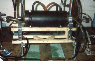
Jonathan Hare with fullerene generator (Sussex Fullerene labs ca. 1990)
Dr Jonathan Hare
THE SUSSEX FULLERENE CENTRE and THE CREATIVE SCIENCE CENTRE
Acknowledgements
I would like to thank the following people for all their help, advice and
experience;
Sir Prof. Harry Kroto, Dr's David Walton, Roger Taylor, Adam Darwish, John
Dennis, Jonathan Crane, Paul Berket, Bernd Eggen and Steve Firth, Jan
Meering and the fullerene Group at the Angmering School (Worthing, West
Sussex, UK), Roddy Vann of St Paul's School (London), Sarah Hogben, Gill
Watson, Caroline McGrath and the expertise and skill of our departments
mechanical engineering workshop.
THIS ARTICLE CONTAINS THE FOLLOWING SECTIONS - Introduction - cluster beam experiments, the carbon arc, solvent extraction, soxhlet
apparatus, chromatography, high purity crystals, brief review of generators Fullerene generator design factors - helium / argon pressures, size of generator, temperatures, arrangements of
the rods, purity of rods, gases and power supplies A high-output soot generator - 'mass production' - description of apparatus, using the generator, common problems and other notes, typical results Soot removal and safety considerations Improving fullerene yields and other experiments Fullerene generator diagram References, notes and other information - fullerene facts and figures, properties of carbon, scientific papers and
notes, information on equipment suppliers.
Introduction
C60, Buckminsterfullerene [1] the third allotropic form of carbon was
discovered in tiny quantities in 1985 by H. W. Kroto (Sussex Uni., UK) and
R. E. Smalley (Rice Uni., USA). In 1990 a method was developed to make C60
(and the family of carbon cage molecules - the fullerenes) in gram
quantities. Fullerene science has now become a rapidly growing field of
research [2]. It is also having an impact in schools, colleges and science
education. By 1995 several schools had actually designed and built their own
fullerene generators [3]. It is these exciting developments in the fullerene
story that have stimulated the following article.
This article briefly describes the fascinating experiments that first
uncovered the fullerenes and the subsequent techniques used to make bulk
quantities of them. Also included are detailed notes on designing a
fullerene generator (which will be of use in schools and colleges as well as
in universities). In particular a stainless steel reactor is described that
can be used to make gram quantities of C60 per day. The design can be
fabricated in a well stocked mechanical workshop in a few days.
Cluster beam experiments
C60 and the fullerenes were discovered on a versatile and ingenious piece of
equipment called a cluster beam apparatus [1,2]. The beam experiments were
essentially very simple; an element (in this case carbon - graphite) was
rapidly heated (under vacuum or inert gas) by a high power laser, reaching
temperatures in excess of 10,000 ░C - hotter than the surface of the Sun.
The vaporised products were then analysed using a sensitive mass
spectrometer. An additional refinement of the experiment was that the laser
vaporised products were rapidly cooled before being fed into the mass
spectrometer, this 'froze' out the reactivity of the various species
produced. Without this many of the species produced would rapidly go on to
form larger systems with their neighbouring vaporised atoms and molecules.
The technique therefore takes a sort of 'snap-shot' of the initial products
of the vaporisation.
The heart of the cluster beam apparatus was the mass spectrometer. This
device separates out all the products in terms of their mass and displays
the result in the form of a graph. This spectrometer makes the machine
versatile and exquisitely sensitive. When carbon was analysed using this
apparatus a whole range of structures (clusters of atoms) were observed, in
fact the spectrum of carbon was just about the most interesting of all
elements. Atoms, small molecules, large molecules, small particles, large
particles and graphite fragments were all observed. At first sight it was
obvious that a random mixture of products were produced by the laser
vaporising the graphite. On closer inspection, certain sized clusters of
atoms appear to be more abundant, stable and resistant to reaction than
others. These 'magic' numbered species were shown to have the closed shell
structures - the fullerenes - with C60, Buckminsterfullerene (the football
molecule), usually being the most dominant [1,2].
There was really only one problem in these fascinating and important
experiments, and that was due to the amazing sensitivity of the
spectrometer. You see, on the one hand this allowed the fullerenes to be
first observed (under formation conditions that were probably far from
favourable) but on the other hand it also meant that only tiny quantities
were actually being produced at any one time. The machine was capable of
detecting nanograms of C60. A rough calculation shows that even if one runs
the cluster beam apparatus for ten years or so, - non stop - one would
barely produce enough C60 to line the bottom of a test tube (perhaps only a
few milligrams would be produced).
This amazing technology therefore puts us in a rather tantalising situation;
it allows us to make new discovers but then leaves us with the problem of
being able to make large enough amounts to be able to do anything with.
Therefore the promising new area of C60 science (for example the physical
and chemical properties) would have to wait until we could make large
quantities - at least on the milligram scale.
The carbon arc
The solution to this dilemma came about with the breakthrough made in 1990
by W. Krõtschmer and D. R. Huffman (a German-American team [4]) and to a
certain extent the Sussex University team [2,5]) using apparatus that might
well have been available back in 1890 ! Unlike the expensive high-tech
cluster beam apparatus that discovered the fullerenes, the apparatus that
first produced gram quantities of C60 was incredibly simple. Bulk quantities
of C60 were first produced using a carbon arc. The technique works like this,
Two high purity carbon rods (roughly 5cm long and 0.5cm diameter) were
supported so that their ends just touched. This rod system was mounted
inside a glass bell-jar. The bell-jar was evacuated and filled with helium
(or argon) to 100 Torr (roughly a seventh of an atmosphere pressure, 700
Torr = 1 atm). A large electrical current (20 volt at about 100 amps) was
then passed through the rods, developing a bright arc-discharge between
them. This was maintained for about 10 - 20 seconds during which time the
arc sputters black soot like material throughout the jar. After letting the
apparatus to cool down the bell-jar was opened up and the soot scrapped out.
The type of deposit found inside the bell-jar depends critically on the
inert gas pressure. Under vacuum a hard, shiny brown graphitic layer was
deposited which was difficult to remove. Introduction of only a small amount
of inert gas dramatically changes the type of layers deposited. For
fractions of a Torr of helium, the deposit settles as a fine jet-black
powdery soot layer or film, which can be removed without difficulty. The
soots remain jet black until the gas pressures reach c.a. 10 Torr, where the
film develops a dark brown hue. On closer inspection these films appear to
have a crystalline component, adding a slight sparkle to the dull soot
layer. Similar results are obtained for argon, although the transition
pressure is a little higher.
Providing the rods were fairly pure (better than a few % purity, ie. no
sulphur content) and that no air leaked into the jar during arcing, 5 - 10 %
of the soot produced in this arc treatment is actually C60. Its as simple as
that !
The fullerenes are soluble
The next step was to try and extract the fullerenes from the arc materials.
Adding toluene (or benzene, hexane, chloroform, carbon disulphide etc) to
the soot and leaving the resultant mixture to stand for a few hours, we find
that the fine suspension of soot particles will settle and the solvent will
have turned red (this was first done at Sussex 6 August 1990, [2,17]). Mass
spectrometry shows that the solution contains C60 and larger fullerenes.
Solvent extraction of the fullerenes is therefore possible. Analysis shows
that C60, C70 and traces of the larger fullerenes make up roughly 80, 20 and
less than 1 % of the isolated material respectively [5].
It is this solubility which allows the fullerenes to be separated
effectively by chromatography (see below) and enables chemical reactions to
be studied systematically and conveniently.
Improving extraction - soxhlet method
Improved fullerene yields were obtained using an ingenious device called a
Soxhlet extractor [5,6] see diagram over the page. The soot was loaded into
a thimble (typically ca. 2 - 3 g of soot; 100 x 30 mm thimble) and placed
into the extractor. Hot solvent condenses and drops on to the soot,
dissolving the fullerenes. Eventually a siphon arrangement draws the
saturated solution away so that a fresh batch of solvent can further extract
the soot. In this way the maximum amount of soluble material can be
extracted. Because of the toxicity of benzene one generally uses chloroform
or toluene. Although fullerene solubility might be slightly lower in these
solvents it does not hinder the extraction process significantly because the
soot is washed many times. Extraction of c.a. 3 grams of soot takes about 2
- 3 hours, and is judged to be complete after the colour stops leaching from
the thimble (although small traces of the larger fullerene > C70 may well
take 10's hours to remove completely). Using this method 5 - 10 % of the
soot was found to be soluble, where the majority of the extract are
fullerenes. The extract solution can then be evaporated to give a
brown-black solid. This extract is washed in acetone to remove hydrocarbon
impurities which may be present from the solvents.
Chromatography
Having found that the extracted material consists of a mixture of molecules
their separation was achieved at Sussex by column chromatography [2,5,6,7].
A chromatography column (glass tube ca. 30 cm long x 1 cm diameter, glass
sinter + tap) was filled with carbon granules (Elorite grade see [19]). The
bottom tap was opened and toluene added until the level reached the top of
the granules and no more was absorbed. The concentrated extract (ca. 30 mg
in 100 ml of toluene) was then passed down the column. When all the extract
was loaded onto the column, fresh toluene was applied. After roughly 10
minuets (from first applying the extract) the first coloured fractions
should emerge from the column. This band is a beautiful magenta colour and
consists of pure C60. Very soon after the first coloured fraction has
finished, a second band appears that is red. This fraction is a mixture of
C60 and C70 (the colour of the former is masked by the latter).
Using this technique, pure samples of C60 can easily be prepared. However
the red C70 fraction will still contain C60 and so further chromatographic
separation has to be carried out on these fractions to produce pure C70.
Chromatography of large amounts of extract (> 100 mg) also produced other
weakly coloured bands following the C70 fractions. These are due to higher
mass (larger) fullerenes present at very low concentrations (ie. see
reference [8] for examples of larger fullerenes > C70)
Further Purification
After repeated chromatography, solutions of relatively pure C60 and C70 can
be prepared (better than 95 percent pure by spectroscopy). The solvent can be evaporated to
leave the solid fullerene. However, the dry solid still contains a
significant quantity of solvent trapped in the crystal lattice.
For example, IR (Infrared) spectroscopy of thin films of C60, show benzene
peaks when evaporated from this solvent. Whatever solvent one uses there is
always trapping in the crystal lattice (perhaps a few % of the mass). One
can substantially reduce this by baking the fullerenes at 550 K for several
hours under vacuum (< 1/1000 Torr). However, defect-free samples of the
fullerenes can only be made by subliming the samples (i.e. heating at ca.
800 K and collecting the sublimate) and then heating for days at a constant
temperature (c.a. 600 K) under vacuum. In this way samples can be annealed
to produce material of high quality.
A brief review of fullerene generators
Various groups around the world have designed and built their own fullerene
generators, and some of these are summarised in the table below. The 'soot
g' column records the total amount of collectable fullerene soot made in one
operation (i.e. each time the apparatus has to be opened up), and the yield
column records the amount of fullerenes extracted from these soot's. Gas
pressures are in Torr.
Note: the laser and induction generator results appear very poor, but one
must remember that these were only preliminary experiments conducted to
confirm that they could be used for making fullerenes, and were not designed
for mass production.
A comparison of fullerene generators
(Group, Arc type, typical He pressures, amount of soot made in one expt.
(g), ~ % yield, comments)
Krõtschmer et al. [4], AC, 100, ~1, ~1, bell-jar
Hare et al. [5,6] , AC, 50, 10, 3-4, steel chamber
Hare et al. [9], DC, 100, 10, 5, vertical chamber
Haufler et al. [10], AC, 100, 1, 10, bell-jar
Parker et al. [11], DC, 200, 10, ~12, steel chamber
Koch et al. [12], DC, 100, 10, 3-4, bench top
Peters et al. [13], RF, 150, 1, 10, induction heating of graphite
Haufler et al. [14], Laser, 500, <1, 20, laser vap. of heated graphite (1200
░C)
Yoshie et al. [15], Plasma, 700, ~1, 7, thermal plasma at atmospheric
pressure
Scrivens et al. [16], DC, 450, ~1, 12, plasma discharge.
Fullerene generator design factors
The carbon arc apparatus used to make fullerenes is essentially very simple.
There are some practical difficulties, however, that make building a
fullerene generator a challenging project. Some of these design features are
discussed below;
1) Best fullerene yields are obtained using helium pressures of about 100
Torr (i.e. ~1/7 atmosphere), although this depends, for example on the size
and shape of the generator (note: argon gives slightly lower yields than
helium). The gas pressure is therefore less than atmospheric and so a
'vacuum tight' chamber is necessary. As a rough guide the system should be
able to pump down successfully to c.a. 1/100 Torr and hold this sort of
vacuum for several minuets (when isolated from the pump).
2) Large chambers may be better than smaller ones. Helium flow experiments
aimed at keeping the pressure inside the apparatus constant while the high
temp arc operates, have been conducted and the results produce slightly
higher C60 yields than static systems. In these experiments helium is
carefully flowed into the chamber at the same rate as it is pumped out. The
effect of the flow is that the system remains at a constant pressure even
though the internal changes in temperature (when the arc is running) are
large. However, fast flows can cause the fullerene production to cease all
together. The change in pressure produced by the heating effect of the arc
may be responsible for lower fullerene yields. Larger chamber may be better
at coping with the pressure changes and therefore give better yields.
3) The carbon arc reaches temperatures in excess of c.a. 4000 K (the arc
melts tungsten) and so the rod-supporting apparatus and the chamber must be
designed to cope with the high temperatures (and large changes of
temperature) while still remaining leak proof. A steel vacuum chamber with
integral water cooling is therefore ideal. A glass bell-jar must therefore
be used with care and can only be used for limited periods.
4) The apparatus must be made so that it can be easily dismantled allowing
the soot to be removed and / or the rods to be replaced after vaporisation.
5) The apparatus must be designed with due regard to the different
electrical potentials of the rods. Usually some kind of insulation is
required (especially on the steel chamber generators). Nylon bolts may be
required for the flanges (at least on one side of the chamber).
6) A two-rod system can be set up when using an AC supply provided that
equal pressures are applied to both the rods when they are pushed together
to be vaporised. If this is not done one rod will burn in preference to the
other. Eventually, if this is not corrected, the rod will continue to burn
back and possibly ruin the apparatus. Also the rods need to be coaxial
otherwise they will pass over each other and limit the vaporisation, or more
seriously damage the apparatus. One will then need to open the apparatus and
replace the rods.
7) A DC arc can also be utilised rather conveniently in a rod-block
arrangement. This is a good starting point for simple bell-jar designs as it
requires the least mechanical workshop facilities. In the rod-block
arrangement a single vertical rod initially makes contact with a large block
of graphite. In a DC arc only the positive electrode is vaporised, therefore
if the block is electrically connected to the negative terminal, while the
rod is connected to the positive, a successful vaporisation can be achieved.
This method has several advantages;
a) a weight attached to the top of the rod is a simple way of always
ensuring a good contact / arc and
b) the arc cannot wander, as experienced in the two-rod system, and also if
the block is made sufficiently large, there are non of the coaxial problems
associated with the two rod design.
However because only one rod is vaporised, the DC system produces about half
the soot of the two-rod system.
8) To increase the amount of soot that can be collected each time the
apparatus is opened up, the design could include a) a system where many rods
can be inserted into the generator one after the other (preferably from the
outside, so that the apparatus need not be dismantled each time), or b) a
system where many rods are fitted internally and used a pair at a time.
9) High grade carbon rods (often called 'spectroscopic grade') were used
for all the experiments which have well known and guaranteed impurity
levels. However, even the cheapest 'low' purity types of these rods (which
have less than 1 % impurities) were found to give the same C60 yields as the
highest purity. Expensive high grade rods are therefore not necessary. Some
details of companies who sell rods are given at the back of this booklet.
10) Some comments on the helium gas. On the whole helium is better than
argon. One school I know actually took the helium out of fair-ground type
balloons ! Although this was a good idea it is very hard to get the helium
into the generator without letting some air leak in. Finally, I am not sure
about the purity of the gas in the balloons - anyway you could try it !
Usually one has to rent a small cylinder of helium from a gas company; the
helium itself is not too expensive but the rental and deposit on the
cylinder can be costly.
If you are really stuck you can try argon from a welding torch set. Again, I
am not sure about the purity but a friendly builder, iron monger may let you
try it for free.
11) A low voltage high current supply is needed to successfully vaporise
the graphite rods. This will depend on the diameter of the rods; 20 - 30
volt at 100 amps works well for ~5 mm rods. A heavy duty car or lorry
battery (12 volt or higher) can be used for these experiments, but they will
need to be continually recharged (possible overnight or longer). This
obviously limits the versatility and amount of material that one can make in
a day and so a mains power supply is really the only practical solution. We
use a welding kit power supply that provides an AC output of ca. 40 - 50
volt at about 100 - 150 amp. DC supplies can be used but only one of the
rods will be vaporised (see (7) above).
Improved synthesis - 'mass production'
The bell jar experiments
Using the bell jar apparatus with a two rod arrangement (5 - 10 cm length, 5
mm diameter) for five experimental runs (about a days operation) produces
about 0.5 gram of soot (roughly containing 25 mg C60). In order to generate
greater quantities of soot (and therefore C60) an improved soot generator
was designed.
On the basis of the points mentioned above a simple generator was designed
and built [17]. In order to produce a simple working system a two-rod AC
system was constructed. The design can be machined in a workshop in a few days.
The carbon rod vaporiser is shown over the page. It consists of a
water-cooled stainless steel chamber (200 x 100 mm OD), fitted with four
ports. Two flanges, mounted on either end of the chamber, are electrically
insulated by plastic (teflon for example) spacers and nylon bolts. The
chamber is vacuum sealed using O-rings either side of the plastic spacers.
The end flanges consist of a water-cooled jacket which surrounds a hollow
tube down which a carbon rod can slide. The carbon rod is vacuum-sealed on
the outside of the flange by an additional O-ring seal. With this
arrangement the carbon rods can be quickly fitted into the apparatus from
the outside without having to dismantle the whole machine. The rods slide
down the water cooled jackets and pass into the chamber where they touch one
another near the centre of the chamber.
305 mm long rods were used (Le Carbone, Purity 8, 4.6 mm diameter [18]), and
so the amount of soot that can be made in one go, is thus greatly increased
over the bell jar. A high current low voltage welder power supply (max. 50
volt AC at ca. 150 amp [20]) was used and connections to the rods made via
the metallic end flanges. Although this means that both the end flanges are
live, the voltage of the welding power supply is low enough (c.a. 30 - 40
volts on load) that it does not represent an undue hazard.
Note: the apparatus should be rested on a non-conducting surface, otherwise
the flanges may short circuit.
The four ports on the main chamber are connected to; vacuum pump (via. tap),
vacuum gauge, mercury manometer and inert gas inlet valve respectively.
There are also connections for water cooling to the chamber and flanges.
A typical run using this apparatus is described below,
Using the generator
The apparatus was assembled and all ports and water cooling pipes fitted.
The carbon rods were then inserted into the flange holes provided. The
O-ring seals were gently tightened so as to obtain a good seal but also
allow some lateral movement of the rods. The rods were then pushed-in to
equal distances so that they meet midway inside the chamber. They were then
separated very slightly (ca. 1 mm).
The tap to the vacuum pump was opened and the chamber pumped down to c.a.
1/100 Torr (this operation takes about 10 minuets depending on how good the
pimp is). The pump valve was then closed and the chamber filled with helium
(via the inlet valve) to almost atmospheric pressure. The inlet valve was
then closed and the chamber pumped out once more. This procedure was
repeated a couple of times to purge air and moisture from the system.
The cooling water is then allowed to run for a minute or two to eliminate
air locks.
Helium (c.a. 100 Torr) was then fed into the chamber by carefully opening
the inlet valve and monitoring the mercury manometer. The power supply was
turned on; no current should pass if the rods have been correctly aligned,
as described above. The commercial welding power supplies tend to be simple
devices (ideal for this application) and switching-on produces a low
frequency buzz from the transformer. When contact is made (and large
currents pass) the buzzing sound increases dramatically so providing a
crude, indication that contact between the rods has been made.
The operator should use plastic gloves as this gives some electrical
insulation and a good grip when adjusting the rods.
With the power supply turned on, one of the rods was advanced slowly so as
to make contact with the other. The power supply then makes a rasping sound
which indicates that the arc has been struck between the rods. It is a good
idea to start a clock at this point and allow the arc to continue for about
20 to 25 seconds. After this the supply is turned off and the apparatus is
allowed to cool for a couple of minutes. The main chamber becomes very hot
while the arc is running (even with good water-cooling) and a cooling down
period is necessary to prevent damage to the system (in particular to the
O-rings and insulating spacers).
After cooling, the process can be repeated, but this time by pushing in the
other rod to strike the arc. By alternating the movement of the rods, the
arc remains roughly central and then one rod will not tend to be vaporised
in preference to the other. While the arc is running, the chosen rod can be
pushed in by hand to speed up the whole process (10 - 15 mm for each 20 sec.
vaporisation's). A pair of rods lasts about 10 to 20 such operations. It is
worth noting here some of the problems which can be encountered when using
the apparatus.
Common problems and other notes
If the rods are pushed in too fast (ie. > 15 - 20 mm per 20 second
vaporisation's) a deposit builds-up on their ends. This increases the
surface area of contact which reduces the current density, which in turn
reduces the amount of vaporisation and therefore lowers the efficiency of
the whole process (also point 6 should be noted here). The best way to
prevent this happening is not to try and rush the vaporisation process; that
is, not to push the rods in too quickly. One can tell if build-up is
occurring because the power supply tends to pass a more steady current and
the noise from the transformer changes from a rasping tone to a continuous
loud buzz. If this happens one can ether open-up the apparatus (as described
below) or try and break off the build-up by carefully pushing the rods
together and twisting them in opposite directions (this time with the supply
off).
Assuming that all goes well and the available length of each rod has been
fed in to the apparatus, the system can be opened. The most convenient way
to do this is to disconnect the water cooling tubes and place rubber bungs
on / in the inlets and outlets (this prevents a horrible mess when it is
time to dismantle the whole apparatus .ps. tell me about it !). Next, open
the vacuum pump valve slowly so as not to dislodge too much of the soot
inside. Leave the pump to evacuate the system for ten minutes or so. It is
advantageous to do this for two reasons; firstly, any toxic gases which may
have been produced in the arc (by an air leak for example) can be removed
safely, and removing the gas tends to compact the soot into a crusty layer
which is far easier to remove later.
After pumping out, the vacuum tap should be closed and the helium inlet
valve carefully opened so that the apparatus slowly regains atmospheric
pressure. The connections to the ports can then be removed. The chamber and
flange assembly will still be bolted together but with little or no rods
protruding and no pipes attached.
Soot removal and precautions
The soot is removed simply by scraping it from the inside of the apparatus.
The best way to do this is to remove one flange and place a piece of paper
over the open end of the chamber, holding this in place the chamber can be
laid on its end and any loose soot is thus confined by the paper. The second
flange (now on top) can be removed and the soot deposited on the flange can
be scraped into the chamber (which now acts as a ready made holder). Finally
a long spatula can be used to scrape the soot off the walls of the chamber.
Lifting off the chamber leaves a pile of soot which can be bottled or loaded
straight into a Soxhlet thimble.
It is advisable to have the whole apparatus mounted inside a fume cupboard,
thus reducing the amount of soot dust. This precaution also protects the
operator from the possible toxic nature of the soot dust. A face mask and
disposable hand gloves also provide protection and should always be used.
The collected soot can now be extracted and the apparatus re-assembled
making sure to clean the O-rings and spacers so that a good vacuum seal can
be obtained.
Typical Results
The apparatus achieved similar yields to those obtained using the bell-jar
(ca. 3 - 4 % yields), however the transition pressure was found to be higher
for the chamber (about 30 Torr instead of 10 Torr) which may be due to the
larger volume of gas used in the bell-jar. The amount of soot produced by
this new generator was of course considerably more (roughly 100 times). The
new vaporisation chamber can be easily used 5 times in a day enabling about
50 grams of processed soot to be manufactured. Over a week, gram quantities
of fullerene extract can be readily prepared.
Improving fullerene yields and further experiments
Some experimental suggestions you might like to consider for improving the
fullerene yields.
Decomposition
Although the fullerenes must be formed from matter condensing from the
carbon arc plasma, it was suspected that UV and heat from the arc might
decompose the fullerenes once formed. A screen arrangement near or around
the arc may be useful in protecting the deposited soots.
Vaporisation arc current
Lower arc currents (<100 amp) were tried by reducing the voltage to the
power supply, via a high power mains Variac.
This was found to reduced the amount of material vaporised. On the whole,
yields were poorer at these lower currents.
Experiments using very high currents (100 - 300 amp) might be worth trying
to increase the fullerene yields (or the distribution of the larger fullerenes).
Vaporisation contact times
Playing around with the length of time for which the arc was maintained
during each vaporisation may effect the distribution of the fullerene
produced and also the yields. For example ten 30 second arcing may give
different fullerene results to say, one hundred 3 second arcs.
AC or DC arc
In our experiments a DC arc was found to produce roughly the same yields as
an AC arc (of similar voltage and current). However, in our experiments we
simply full wave rectified the AC voltage from the welding kit power supply.
No regulation or smoothing was applied and so the current was not strictly
DC; it effectively behaved as a 100 Hz pulsed DC system rather than as
smoothed DC. A car (or better a lorry) battery may work, although you will
have to recharge them regularly.
[1] H. W. Kroto, J. R. Heath, S. C. O'Brien, R. F. Curl, R. E. Smalley,
Nature, 1985, 318, 162.
[2] H. W. Kroto, C60: Buckminsterfullerene, The Celestial Sphere that Fell
to Earth,
Angewandte Chemie, 1992, 31, 111 - 246.
[3] J. P. Hare, Sussex University, C60 and Schools, Past Sixteen Science
Issues, Feb. 1996.
[4] W. Krõtschmer, L. D. Lamb, K. Fostiropoulos, D. R. Huffman, Nature,
1990, 347, 354.
[5] R. Taylor, J. P. Hare, A. K. Abdul-Sada, H. W. Kroto, Journal of The
Chemical Society,
Chemical Communications, 1990, 1423.
[6] J. P. Hare, R. Taylor, H. W. Kroto, Chemical Physics Letters, 1991, 177,
394.
[7] A. D. Darwish, H. W. Kroto, R. Taylor, D. R. M. Walton, Improved
chromatographic
separation of C60 and C70,
Journal of the Chemical Society, Chemical Communications, 1994, 15 - 16.
[8] See articles in Physics and Chemistry of Fullerenes, Editor P. S.
Stephens,
Advanced Series in Fullerenes, Vol. 1, World Scientific Publications, 1993,
ISBN 981-02-1117-1.
[9] A vertical rod-block generator with a large volume (ca. 10 litre)
stainless steel chamber.
[10] R. E. Haufler, Materials Research Society, Symposium Proceedings, 29th
Nov. 1990.
[11] D. H. Parker, P. Worz, K. Chatterjee, K. R. Lykke, J. E. Hunt, M. J.
Pellin,
J. C. Hemmiger, D. M. Gruen, L. M. Stock, Journal of the American Chemical
Society, 1991, 113, 7499.
[12] A. S. Koch, K. C. Khemani, F. Wudl, Journal of Organic Chemistry, 1991,
56, 4543.
[13] G. Peters, M. Jansen, Angewandte Chemie, International (English)
Edition 1992, 31, 223.
[14] R. E. Haufler et al. Material Research Society, Symposium Proceedings,
1991, 206, 627 - 637.
[15] K. Yoshie, S. Kasuya, K. Eguchi, T. Yoshida, Applied Physics Letters,
1992, 61, 2782.
[16] W. A. Scrivens, J. M. Tour, Journal of Organic Chemistry, 1992, 57, 6932.
[17] J. P. Hare, PhD Thesis, University of Sussex, Chemistry and Molecular
Sciences, 1993.
Carbon rod suppliers
[18] Le Carbon, South Street, Portslade, Brighton, East Sussex, BN41 2LX.
Tel. 01273 415701, Fax. 01273 415673. Purity 6 rods,
4.6 mm diameter x 303 mm long, ca. ú 200 for 100).
Agar Aids Ltd, 66a Cambridge Road, Stansted, Essex, CM24 8DA
(for small high purity rods, Type E340, 5 mm diameter x 50 mm
ca. ú10-00 for 10).
Chromatography suppliers
[19] Toluene need not be high purity.
Fissons may sell an appropriate column
Carbon granules from;
Norite Ltd, ELORITE grade, carbon granules, sample number A-8160, Norit
N. V., Postbus 105, 3800 AC, Amersfoot, The Netherlands.
AC welding power supplies
[20] RS components, Turboweld 8, SN 623-271, page 3-3125 Radio Spares Catalogue
or borrow one , have one donated, or steal one from a builder, ironmonger
or garage.
or try a fully charged car battery.
11-07-96 JPH, fullgen1.doc, last changes 12-09-08
THE CREATIVE SCIENCE CENTRE
Dr Jonathan Hare,The University of Sussex
Brighton, East Sussex. BN1 9QJ