Introduction
Living in the city there is a lot of noise at very low frequencies (VLF ca. 10-100kHz) due to computers, plasma TVs, switch mode power supplies etc. Noise can be picked up at all angles and over a wide range of frequencies. As a result directional antennas, such as ferrite rods and loops, can not always improve the signal to noise.
At my location I can hear these signals when I tune around on CW setting, as heterodyne whistles. At night I have particularly strong interference at 63kHz which is so strong that I can not receive the MSF signal on 60kHz at all. I designed this crystal filter to try and solve this problem.
Description of circuit
The heart of the filter is a small 60kHz crystal (Farnell, e-bay) [1]. The first IC simply acts as a unity gain buffer that passes the signal from the antenna into the crystal. The buffered o/p feeds both the crystal and a small pre-set capacitor (ca. 5-10pf). These two signals go into the non inverting and inverting inputs respectively of an instrumental amplifier (inst. amp.).
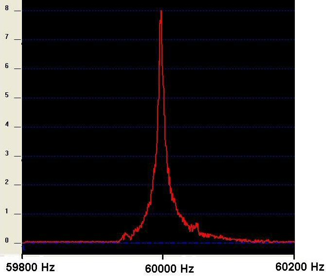
The pre-set capacitor is used to balance-out the internal capacitance of the crystal (off-frequency it looks like a small capacitor ca. 5-10pf). When the pre-set capacitor is correctly adjusted, signals away from resonant frequency (60kHz) should cancel. At resonance however the signals no longer cancel and we should get an o/p from the second amplifier. The results is a narrow band pass filter (BPF) with a pass band at the resonant frequency of the crystal. I set the inst. amp for x 10 gain (5k6 between pin 1 and 8 of the INA118) so that the circuit provides a little gain to counter any loss through the crystal. I used 8 pin chip holders for the ICs but once you are happy with the performance it might be worth soldering in the IC directly.
Setting up
The input impedance of the inst. amp. is very high (1010 ohm) and so does not load or damping the crystal. The result is that the filter response is very narrow. If we listen to the MSF transmission on a receiver we find the o/p sounds like it is 'ringing'. I added a 1M resistor (marked with * on the circuit) to damped the crystal response so that it can respond well to the slow code on the MSF signal. Some experimentation may by needed here.
The pre-set capacitor also has a 1M resistor to 'ground'. I found this was needed to eliminate DC offset voltages which cause the amplifier to saturate (turn completely ON or OFF) when the amplifier has some gain (e.g. x 10).
The 'ground' is produced by two resistors across the supply creating a half supply voltage we can use as the amplifiers zero reference (Note: this also goes to pin 5 the ref pin of the inst. amp.). The two resistors effectively eliminate any large offsets that might results if the inputs are left 'floating' with only the capacitance and crystal connected.
The INA118
The INA118 Inst. amps is a great device but compared to a standard op-amp, relatively expensive. I happened to have a few left over from other projects so I used it here. The data sheets claim a wide supply range, very low current consumption and a gain of x100 at 70kHz. So there is scope for higher gains if the experimenter thought it was necessary. If your budget can't stretch to this a second CA3140 could be used to create a differential amplifier using 1M input resistors and 10M feedback resistor to give x -10 gain (The input resistor would also provide damping for the crystal).
I found that the setting of the pre-set capacitor was not critical and seemed to give best performance when it was set almost out of circuit (minimum value). Some experimentation may be worth undertaking to find the ideal value for your particular crystal to give best out-of-band rejection (see below).
The circuit must be housed in its own metal (screened) box and the power supply properly decoupled. A small hole can be drilled in the lid so that the pre-set capacitor can be adjusted. Both the INA118 and the CA3140 should work down to quite low voltages and this circuit should work well on ca. 9-12V.
At night (which is the most noisy time) you can hear that everything is very much quieter with the filter in-circuit and the MSF signal is much stronger. Without the damping resistors the circuit 'rings' (it sounds as if you are listening to the transmission in an echo chamber, subway or long concrete pipe) making the MSF time code difficult to discern. You can experiment with R* to get a suitably narrow response (1M to 10M).
Notes and references
[1] I got a bag of five small surface mount 60kHz crystals from e-bay (originally from Farnell) for Ł16. I soldered two short wires to the crystal and used them to support and electrically connect them into my circuit board.
[2] I love the INA118 instrumentation ampifier. It has at least x100 gain at 60kHz, very good balancing properties and runs on a very wide range of supply voltages at low current. You can purchase them at RS components or through e-bay etc.
JPH, Feb 2012
THE CREATIVE SCIENCE CENTRE
home | diary | whats on | CSC summary | latest news