Simple radio with 3D printed base

This is a very simple radio that derives its power from the signal picked from the antenna so it does not need a battery. The radio uses a very sensitive crystal earpiece (ordinary headphones will not work) but even so programs picked up by the radio will not be very loud in the earpiece. In general the longer the antenna wire the better the performance - you will need at least 10m of wire, but 20 - 30m would be better (any copper wire will do). The radio will usually work better if a connection to ground (Earth) is made - but this is not essential. The earth wire can be a connection to a house radiator or a copper pipe driven into garden soil etc.

The radio has the following parts:
Tuning coil: about 40 turns of enamalled copper wire on a 6cm diameter tube (plastic or cardboard)
Tuning capacitor: 300 pf variable or equivalent
Crystal earpiece and (3.5 mm mono) socket
about 10 - 30m of wire for the antenna and a small length (few m) for the earth wire
Germanium diode (sometimes called a crystal diode) e.g. OA91 or AA119.

Follow the directions below to make the radio:

photo of radio

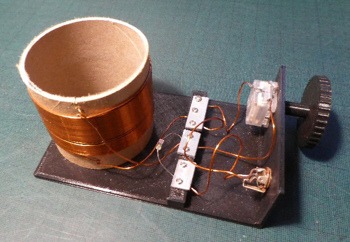
The complete 'crystal' set radio using a 3D printed base, 3D printed capacitor knob and a part 3D printed connector block

circuit of radio

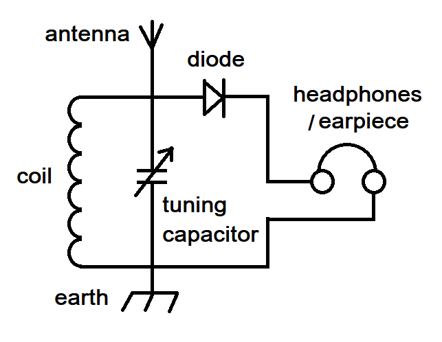
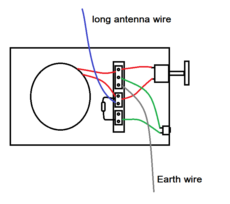
'crystal' set radio circuit diagram showing the coil, capacitor, diode, antenna, earth and earphone symbols.


basic layout

The basic 3D printed base from which we are going to build our radio.
On the left we have a place for the large coil, on the right there is an up-right panel that holds the tuning capacitor and the earphone socket.


basic layout

Making the coil: you need about 8m of enamalled copper wire to make the coil (I used 20 SWG copper enamelled wire but almost any will do). I used a 6 cm diameter cardboard tube to wind the coil on but a short off-cut of plastic water pipe or even the cardboard center from a loo roll can be used. Smaller tubes will need more turns. Carefully wind this wire around the cardboard former as neatly as you can remembering to leave wire free at both ends to connect to the rest of the radio. Start by threading the wire through two small holes in the bottom of the tube (see picture above) so you have about 6cm or so free. Then wind the rest of the wire around the former and thread the end through the top holes to secure (so it does not unwind). Note: the wire is called enamelled wire which is a copper wire which has a very thin layer of enamel insulation on it. The insulation is very important, without it the turns of wire would all short circuit.

IMPORTANT: you need to make sure you remove the thin insulation at the very ends of the coil so we can electrically connect to it - you can use a pen knife or perhaps better fine sandpaper.


basic layout

Wiring the capacitor & the coil (wires shown in red): connect the two wires from the tuning capacitor (many tuning capacitors have three connections on them: the middle is the earth connection the other two can be joined and used together) and the two wires from the coil together by trapping the ends under the metal connector (top of the three). Note: make sure the end wires are clean and free from insulation - we need the copper wire touching the metal connectors not the thin insulation. Ideally the wire going to the middle connection on the capacitor should go to the long metal connector (the one with the three screws shown at the top of the diagram), the other wire goes to the middle connector.


basic layout

Wiring the earpiece socket (wires shown in green): one wire goes under the three way metal connector, the other wire goes to the third metal connector that has not been used yet.


basic layout

Adding the antenna & crystal (OA91) diode: connect the diode (either way around) under the middle and third metal connector. Connect the long antenna wire under the middle metal connector. Once you have checked all the connections and carefully tighten all the screws to secure the metal connectors, then plug in the earpiece and slowly turn the tuning capacitor knob to see if you can hear any local radio stations.


basic layout

Adding an Earth connection: adding a wire connection (as shown above) to a copper radiator pipe or other 'Earth' connection can often improve reception results.


A bit about how the crystal set radio works
Radio waves are travelling around and passing through us all the time. These Electromagnetic (EM) waves (composed of electric and magnetic fields) are usually weak and so are not harmful. When a radio wave passes through a conductor like a metal, the wave creates alternating currents and voltages in the metal (called RF radio frequency signals). A device that converts the EM wave into an electrical current is called an antenna or aerial. Every metal object can therefore act as an antenna even metal framed glasses or bicycle handle bars!

This RF voltage is far too high in frequency to hear if you wired it into an earpiece. To hear the radio waves you need a device called a diode, or rectifier. 100 years ago this was often made from a small piece of a mineral called Galena (lead sulphide) but burnt coal (coke) and even rusty razor blades have been used to make a simple rectifiers. The crystal of galena lead to the radios become known as 'crystal set radios' or 'xtal sets'. Before we can use the diode detector to hear the radio stations we need a way of tuning the radio. This is done using a very simple circuit called a tuned circuit that uses a coil of wire and a tuning capacitor.

The coil of wire is simply that; a spring like coil of insulated wire closely spaced together. A capacitor is a set of closely spaced metal sheets or plates that do not touch, the sheets can be moved (rotated) so that you can adjust how much they overlap with each other. If you pass an electrical current through a coil of wire it creates a magnetic field in the coil - energy is stored in the magnetic field. If you apply a voltage across a capacitor energy is stored in an electric field created by electrical charges opposite each other on the metal plates. If you wire the two together and apply an RF signal from an antenna energy only efficently gets transfered at one frequency - the so called 'resonant frequency' of the coil and capacitor. This will be the signal frequency that will make it through the circuit and will pass through to the diode to rectify it to hear the radio program in the earpiece. As the capacitor can be adjusted by varying the overlap of the metal plates you can 'tune' the radio by adjusting the capacitor - hence tuning capacitor.

So in summary: a wire antenna produces an RF voltage from the electromagnetic waves and the coil and capacitor wired to it allows only a small range of signals to pass through (one radio station). This signal is then wired to a diode to rectify the signal which strips off the music and voice from the radio wave. This audio frequency voltage then drives the earpiece which converts the voltage into sound that we can hear :-)


references and links
Wiki page in Crystal set radio

The Xtal Set society

Rough Science saucepan shortwave crystal set radio

Good books:

'Making a Transistor Radio' by G C Dobbs, Ladybird Book
very old but a wonderful book and a good explanation of the crystal set in the first half of the book - worth getting a copy via an on-line second hand book site.


THE CREATIVE SCIENCE CENTRE

Dr Jonathan Hare, The University of Sussex
Brighton, East Sussex. BN1 9QJ.

home | diary | whats on | CSC summary | latest news