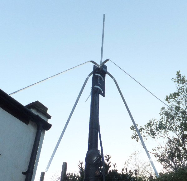
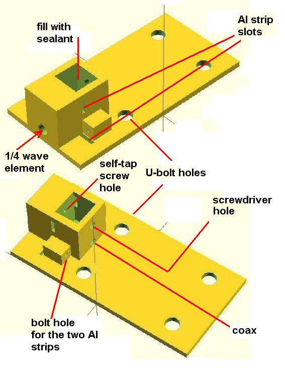
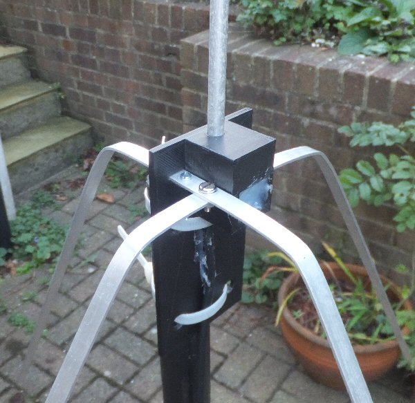
144 MHz ground plan (GP) antenna using a 3D printed center

series


The ground plane (GP) antenna is a quarter wave vertical with four quarter wave ground radials. Here I have 3D printed a center unit that will take a 1/4 wave 48cm (19") 8mm diameter tube and two 1m long 10 mm wide aluminium strips which are used to make four 1/4 wave radials. The 3D base includes a square box section that is used to connect to the elements which can then be filled with sealant once everything is connected up. The vertical tube slots into the top of the base while the two Al strips slot in to the side of the box. I have also included a hole to allow thin 50 ohm coax into the box. Solder tags are soldered on to the inner and outer of the coax and these go to the elements. The tag connected to the inner of the coax is attached to a hole in the vertical tube via a self tap screw (this can be done using a screwdriver from above). The outer coax connection solder tag goes to the center of one of the Al strips using another self tap screw Note: because of the arrangement this has to be screwed in via a hole I have printed in the side of the box. The second radial set attaches to the first radial via a nut / bolt just out side the plastic box (so it is very slightly offset from the outer coax connection). A second bolt goes through the second strip via a 3D printed support on the left hand side of the printed base.

series
Once all the connections are secure you can test using an ohm meter at the end of the coax that there are no short circuits or open circuits. The inner of the coax connects directly to the vertical rod while the outer of the coax should show low conductivity to the radials. Once this has been checked and found good the box can be filled with sealant (e.g. silicon sealant or even glue gun). Put a piece of tape over the screw driver hole so that the sealant does not pour out at this point. Remember to put a plastic cap on the end of the vertical tube (or fill the top 3cm or so with sealant) to stop water getting in. You could cover up the sealant filled box with black tape to make it look better. The photos show the antenna supported by cable-ties but I have designed it to be used with U-bolts (36mm inner) but remember that the base mounting bracket is made of plastic so be careful not to use too much force on the nuts.

I attached a few m of RG8 mini to the antenna and checked the SWR. It was below 1.7:1 on 144 - 148 MHz. You can easily change the angle of the radials by bending them all downward and fine tune the SWR to get less than 1.5:1 over the 2m band. You really need to do the SWR measurements at the antenna but if this is not possible then try to use an even number of half wave length of cable between the antenna and SWR meter. I used an old piece of 8mm tube salvaged from another antenna experiment, while the aluminium strips came from the local B&Q store.

I have been using this antenna for the Worthing and District Amateur Radio (WADARC) Monday nets.


series


".stl" file
".g" file
".scad" file
my radio
page
my antenna
page
more
soon
back to
3D page


THE CREATIVE SCIENCE CENTRE


Dr Jonathan Hare University of Sussex, Brighton.
e-mail: j.p.hare@sussex.ac.uk

home | diary | whats on | CSC summary | latest news