Using a Pi Pico to send-receive IC-V data to Icom transceivers
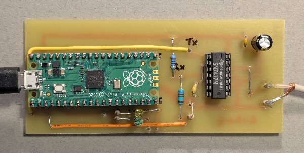
Pi Pico used to send CI-V data (with 7417 TTL buffer) to IC7300 or IC9700 Radio

| Radio | Addresss (hex) |
| IC7300 MK I | 94 |
| IC7300 MK II | B6 |
| IC9700 | A2 |
| Radio | Addresss (hex) |
| IC7300 MK I | 94 |
| IC7300 MK II | B6 |
| IC9700 | A2 |
A Pi Pico can't be connected directly to your Icom transceiver via the CI-V line at the back of the radio - we need an interface. The CI-V line is two-way having data going from the Pi Pico to the radio as well as data going from the radio to the Pi Pico (but not at the same time of course). Ideally we need an interface that will i) cope with the voltage difference between the Pi Pico and the radio, ii) not stop data being sent from the radio when the Pi Pico is idle, iii) can split the Tx and Rx signals to go seperate Pi Pico GP pins and iv) cope with the correct baud rate speed etc.
The Pi Pico UART idles high (3V) and data is sent when it drops to 'zero'. ChatGPT suggested various interfaces to go from the Pi Pico to the Icom radio but many were simply a single transistor inverter. Not only will this invert the UART data but when it idles high it will essentialy ground the CI-V line stopping other traffic being able to be sent along the IC-V.
I tried a few interfaces but this one using a 7417 buffer (from W8WWV's Icom interface, see link below) has worked with the Pi Pico projects perfectly.
Note: R1 is a little low in value, I guess he used this to get maximum speed. but as we are using a relatively low 19200 baud rate R1 could probably could be raised to 1k or even perhaps 4k7
- it's experimental and a higher value might be safer for your rig (you could also try adding a 100R in series with the CI-V output to the radio).

Note I: as the interface input is connected to it's output, you will receive back into the UART buffer everything you send out. So in the code remember to delete the buffer immediatly after sending out data to the radio (or at least compensate for this - the UART buffer is not very large on the Pi Pico).
Note II: once you set-up the UART in the software, it will receive even if your code is not using it, so the buffer can easily fill up with CI-V traffic from the radio.

Prototype code can be found below that allows the Pi Pico to request the frequency from an IC7300 (MK I or MK II). This information is then used to power RF relays to switch in correct antennas for the wide range of frequencies these radios can cover ('top band' to 4m). NOTE: We have found some issues using this set-up with a networked radio being used remotely. It appears that the CI-V traffic from the Pi Pico can sometimes clash with that from the software used to control the radio. So please bear this in mind - its prototype software - 'work in progress'.
In the S-meter project I have sent out the S-meter data value as a pulse width modulated (PWM) signal on GP16. You need a simple low pass filter (LPF) to 'average' this into a DC signal which you can send to a data logger (see circuit above). It would be a good idea to have a unity gain (op amp e.g. TL071 or LMC6482) buffer between the output of the LPF and the data logger. The micro python used on the Pi Pico has a built-in file system which can create comma seperated veriable (CSV) files, and so I am also working on building this into the S-meter project (more soon).
When you request an S-meter reading via CI-V, the frames that come back are often delayed (sometimes by many seconds) further more the value that comes back may not mirror exactly the value shown on the front panel meter. Its seems the S-meter value sent back via CI-V is an average of the meter readings. S0 to S9 +60dB comes back as 'vales' of 0-255 in binary coded decimal. So in principle S0 will give back '0', S9 gives about "120" and S9 + 60 dB will give '255'. The value comes back in two bytes in the S-meter request CI-V frames. So in the S9 + 60dB case i.e. '255': one byte will contain '2' and the other '55'. If you multiply the '2' (hex) x 100 and add it to the '55' (hex) you will get the full value of 255 (decimal). The numbers might be hex but A - F are never sent, only binary coded decimal are actually ever sent.
Note 1: The S-meter value (0-255) sent back along the CI-V frames is not linear with the S-meter reading (it may not be 6dB per S-unit either). There are semi-accurate formula (e.g. dB above S9 = (raw-120)/3, see my code) that will convert the raw value into an equivalent S-meter value but they are very rough. You could use a look-up table etc. Either way, with this prototype set-up you can at least log a beacon or station and see how the signal is improving or diminishing over time. You could either calibrate the raw values coming back using the front panel meter reading or better still measure the raw values against a know calibrated signal source etc.
Note II: it is best to set-up the radio and tune into the station / beacon you want to log and only then turn on the pi-pico circuit and interface. Then leave everything as it is. If you change the frequency setting or make other changes it can stall the software. Changing the pre-amp / attenuator setting seems to be ok.
Note III: the signal strength comes back as a 0-255 number, which is a much higher resolution than just looking at an s-meter 'needle'. It would probably be worth converting the raw signal strength date into dBm (power) rather than using s-meter units.
Note IV: you soon find that the weak signals raw values are 'all over the place'. My next projects then, is to do a bit of signal processing on the raw data - e.g. record say 10 or 20 raw values and do 'mean, median and mode' analysis on each batch of data (e.g. median would remove the noise peak and CW off outliers).
Please read the notes written on the python code as they tell you which Pi Pico pins to use as well as other important information.
|
back to Radio page |
S-meter code |
request freqency code Notes (PDF) |
W8WWV Icom interface |
back to pi Pico page |
THE CREATIVE SCIENCE CENTRE
home | diary | whats on | CSC summary | latest news