FOUR/ FIVE TURN 1m LOOP ANTENNA
FOR 80m (and 160m)
I have been Rx on 80m with home made Direct Conversion recievers since 1980's. Unfortunately I can't have full sized 80m antennas on my present city location so I have been experimenting with loops and found them to be very good Rx antennas. They have a useful null and provide a wonderfull drop in noise to bring the DX in! Here is a link to a small receiving loop
This following antennas were inspired by Harry Lythall (SM0VPO) 'flat-dwellers' frame antenna which he uses for Rx (and low power TX) on 80m and 160m. I have only tried it on the 80m band. Below are some close up pictures of my version. I found I had to remove one of the turns. The first few photos are of my copy of his design followed by my modifications and experiments.
According to John Kraus (the antenna pioneer) the impedence of a small n-turn loop (small compared to the wavelength) is dependent on n2. The 'DC' resistance (effective DC resistance after the skin-effect has been considered) will be dependant on n. So I was hoping that a n-turn (n=4 in this case) might have some advantages over a single turn loop. The first advantage is that because the 4 turn loop has a higher inductance than a single turn, the capacitor can be much smaller for the same resonant frequency. It's much easier to make a small capacitance wide-spaced capacitor which will (I hope) cope with the high voltages on Tx. I hope the later versions e.g. the 8mm copper tube (see below), will radiate something! All versions are great Rx antennas.
This loop might make a nice antenna for CW or for PSK31 experiments on 80m for example, especialy for those like me who dont have much space for antennas.

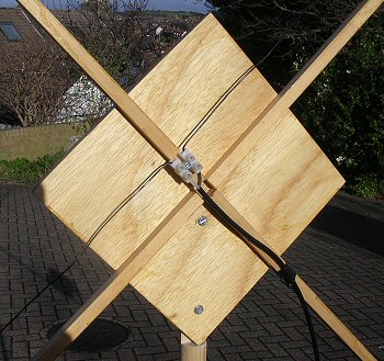
The completed copy of the frame antenna. It sits on a weighted tripod and can easily be rotated for null.

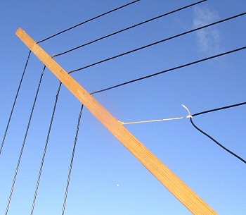
Showing a corner of the loop and also part of the coupling coil positioned using nylon cord. The wires are feed through holes drilled in the four spreader arms.
The wood structure was varnished after assembly which also helped to secure the windings.

Showing the high voltage capacitor with reduction drive and waterproof enclosure.
The loop connections go in at the bottom of the box through long sleeve rubber gromets.

Connection of the 50 ohm coax to the triangular coupling coil.

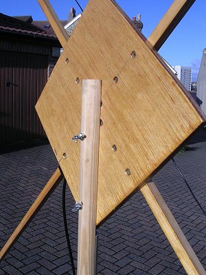
The central support showing the butterfly nut fixing to the tripod mast.

Another version of the loop made from plastic water pipes and connections. You can just make out the motorised capacitor through the window of the waterproof box. I made a wooden version of the outside loop but although it was varnished a couple of times its performance degraded over the months which I put down to water absorption in the wooden framework (the Q reduced and it became 'deaf'). I am hoping this plastic version will last longer. I use this only for 80m Rx (the capacitor is too closed spaced for Tx). I have since made the wires to the capacitor much more tidy - which I hope will improve the null.

In March 2010 I change the 'household' type wiring for solid 12 SWG enamalled copper wire and changed the capacitor for a more
wide-spaced device. I also changed the coupling coil for a RG58 coaxial faraday screen type (at center, ca. 140 cm circumference - gave very good SWR on 80m band).

In the summer of 2010 I changed the faraday coupling coil for heaver RG8 cable and also changed the capacitor for a home-brew wide-spaced (8mm spacing) double-gang design. The capacitor is now effectively two veriable capacitors in series, which means that the moving vanes don't need to be connected to any wires (i.e. the two loop connections go to the fixed parts of the two capacitors). The antenna now covers ca. 3.6 - 4.0 MHz and seems to cope with 10's Watts all ok.

In October 2013 I changed the 12 SWG loop wire for a single piece of 8mm copper tube (about 30', 10m length).
I used the same home-made wide-spaced capacitor and RG8 faraday coupling coil. I hope that I may now be able to experiment with using this loop for low power Tx as well as Rx.
4sqrp News Letter article August 2012
Some thoughts about the 80m band
home-made tripod details
Dr Jonathan Hare, E-mail: jphcreativescience@gmail.com
NOTE: Although none of the experiments shown in this site represent a great hazard, neither the Creative Science Centre,
Jonathan Hare nor The University of Sussex can take responsiblity for your own experiments based on these web pages.
THE CREATIVE SCIENCE CENTRE
home | diary | whats on | CSC summary | latest news


