Full size lightweight 10m band dipole
for top of 15m fibreglass mast
(for more details see RadCom Basics: 3D printing, J P Hare, RadCom Basics, 2026 in press)
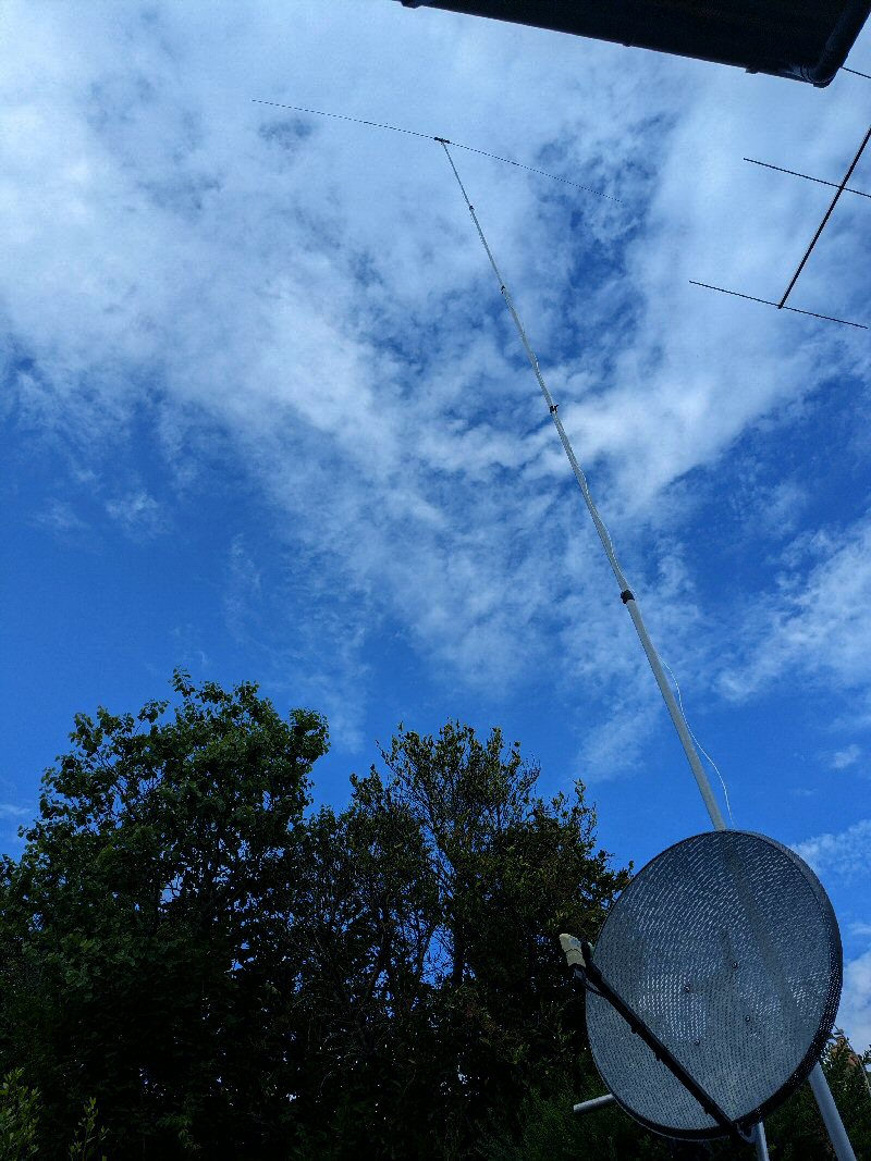
I wanted to make an experimental lightweight full sized dipole that could go on top of my base supported 15m fibreglass mast. When not in use it would be taken down and stored away (i.e. it did not need to be a permanent outside design). To reduce load upon the mast I needed to keep the weight down so I also used 90-ohm twin feeder instead of coax. The total weight of the 3D printed center and the aluminium rods / tubes is only about 500 g.
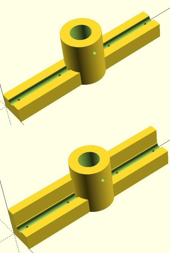
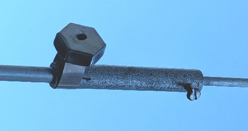
I used a 3D printed dipole center for the prototype, the files are below so you can print out your own. The design includes a fitting to go on the top 23 mm diamater tube of my mast. Using a butterfly bolt (or go-pro screw) you can pop the center on the mast and tighten the bolt to secure it.
My first prototype (top image on the diagram) was made in PLA , however over time the weight / leverage of the two dipole element caused the central 3D printed part to bend.
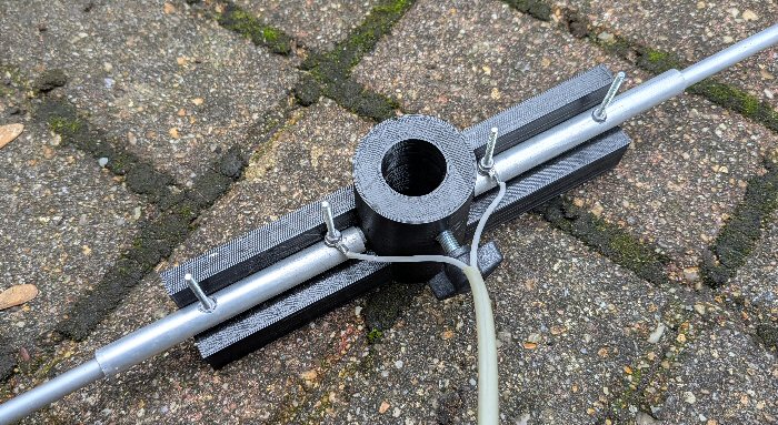
In the second version (bottom image on diagram) I added more support, see the photos. For longevity ASA filament would be much better choice for permanant outside applications,
it is a similar to plastic water gutter material, so has better UV stability and thermal stability than PLA.
Each half of the dipole is made from two lengths of aluminium tube / rod fitted together to make up the ca. 2.5m length required (5m in all for a 10m band dipole).
The ends of the two 1m 8mm diameter tubes fit into the grooves on the 3D printed center and are fixed in place using bolts (see photos).
Note 1: drilling the tubes makes them vulnerable and one day a bird flew into one of the elements and broke it clean off. To overcome this I added two short pieces of slightly larger (10-12 mm) tube at the centre, this moves the strain from the bolt holes to the outer edge of the short tube.
Each 8mm tube has a ca. 1.5 m long 6 mm diameter rod attached to them. You may get away with slotting the smaller diamater rod into the larger tubes. Mine did not quite fit, so I made up two adaptors using short pieces of rod with a securing screw and hose clip to join the two together (see photo). Even if you can slide the rods into the tubes, you may find they can get stuck, so if you want the antenna to be easily dismantled, the adaptors are a good idea.
The use of 90-ohm twin feeder instead of coax and a proper balanced ATU means I can use the dipole over the whole of the 10m band, it also seems to work well on the 12m and 18m bands.

Dr Jonathan Hare, E-mail: jphcreativescience@gmail.com
NOTE: Although none of the experiments shown in this site represent a great hazard, neither the Creative Science Centre,
Jonathan Hare nor The University of Sussex can take responsiblity for your own experiments based on these web pages.
THE CREATIVE SCIENCE CENTRE
home | diary | whats on | CSC summary | latest news