**** IF YOU SPOT ANY MISTAKES OR ERRORS PLEASE LET ME KNOW ****
Torsion Balance Experiments
The torsion balance can be used to create very sensitive scientific instruments. In 1798 Henry Chadwick used the torsion balance to create apparatus to estimate the universal gravitational constant (G) and similar equipment was used to estimate the mass of the earth. Later the torsion balance was used in the mirror galvanometer which revolutionised detecting the tiny signals sent down the first transatlantic cables in the 1850's.
The basic theory (ignoring resistance / frictional losses)
If a bar or wire is twisted there will be a force tending to return it back to the original position. This 'restoring force' is proportional to the product of the angle of twist (θ) and a constant called the Torsion Constant (N).
The torsion constant is dependant on the type of material and the length, demensions and shape of the bar or wire (e.g. circular or rectangular cross section etc.).
The restoring force is therefore given by F = - Nθ ............. [1] (θ, in radians)
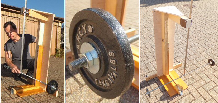
If we attach two masses each M kg and r meters either side of a flat bar (see diagrams above) the system will be balanced and can oscillate back and forth. This is an example of a torsion balance and the flat bar is the torsion spring.
The forces on the moving masses is given by the moment of inertia (I) x acceleration (A).
This is the same value as the restoring force (torsion constant x angle) so we get:
Nθ = IA ............. [2]
which on rearranging gives:
A = Nθ/I ............. [3]
For simple harmonic motion (SHM) the acceleration (a) is proportional to minus the displacement (x)
a = ω2x (ignoring signs) where w is the angular frequency
ω=2πf = 2π/T, where f is the frequency (Hz) and T is the period (seconds)
We treat the torsion balance movement as simple harmonic motion (SHM) or as a simple harmonic oscillator, but now the restoring force is proportional to minus the angular displacement:
A = ω2θ which with equation [3] gives:
A = Nθ/I = ω2θ
so ω = √(N/I)
as ω = 2πf or ω = 2π/T
we get the period T = 2π√(I/N) ............. [4]
which on squaring gives:
T2 = 4π2(I/N) ......... [5]
Note: we use T2 instead of T as it removes the complication of the square root sign.
Total moment of inertia
We need to determine the moment of inertia (I) of the system to get any further. Because the two weights are not spherical, like in a classic dumb bell arrangement (two balls separated either side r from the center of axis) but flat discs I am making the approximation that the flat weights approximate to the two mass being at points r away along the bar from the axis. This should be close to I = 2Mr2 (M being the mass of each identical weight).
The moment of inertia of the support bar is I = bL2/12, see wiki link here for details and all sorts of other examples.
Where b = mass of bar, L = total length (1m).
For two flat weights approximately r away from the axis Iw = 2Mr2
For a thin studded support bar Ib = bL2/12 (see wiki page link)
as these are in the same plane and have the same axis of rotation we can add them together to get the total I:
I = Iw + Ib = 2Mr2 + bL2/12
putting this into the period equation [5] we get:
so T2 = (2π)2/N x (2Mr2 + bL2/12)
Note: we use T2 instead of T as it removes the complication of the square root sign.
and expanding this to create a 'straight line graph' format we get:
T2 = [8π2M/N] r2 + [π2bL2/3N]
y = [m]x + [c]
so a plot of T2 against r2 should give a straight line with:
a gradient of m = 8π2M/N
and y intercept of c = π2bL2/3N
from this we can for example estimate the torsion constant (N) and the mass (b) of the support arm:
N = 8π2M/m
b = 3NC/(4π2L2) = 3CM/(L2m)
First results - some data
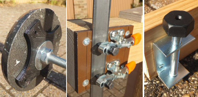
Left: the back of one of the training weights with a 3D-printed adaptor.
Middle: the two small clamps that hold the torsion spring - the thin steel bar / strip.
I used tuffnel sheets to provide a rigid surface to clamp on to.
Right: one of the three screw feet that can be used to level the apparatus.
First Results
I made up a solid wooden structure to hold all the gear, see top photos. I used two clamps to hold the metal torsion strip to the top of the structure and drilled the bottom end to take the 10mm studded support bar (1m long). Nuts secured the bar to the strip. The training weights have a large hole in the middle (ca. 35mm) and so I 3D-printed adaptors so that the weights would more easily and securely slide-on to the studded bar (with two large washers). The two masses were 0.5kg cylindrical training weights. The mass of the studded support bar for the weights was b=0.45kg and was L=1m long. The torsion spring for these first experiments, is a thin mild steel bar 1m long, 20mm wide and 2mm thick (B&Q type 2001-61925) and in this first test set-up I clamped it so the length used was H = 0.68 m.
I fitted the weights at various distances (r) away from the center and then set the torsion balance in motion (being careful not to create a wobble or swing from side to side, but rather a twisting back and forth). I let it settle down for a few cycles (so any transients might decay) and then recorded the time for 50 swings / cycles. Then of course I divided this time by 50 to get the period of oscillation T. In this way T was determined for various values of r (T in seconds and r in meters). I havent included any comments or analysis of possible errors here. Note: for the r=0 measurement I simply removed the two weights and measured the period of the empty support bar *.
|
r(m)
|
r2
|
T (50 cycles)
|
T (seconds)
|
T2
|
|
0
|
0
|
27.0
|
0.54 *
|
0.29
|
|
0.1
|
0.01
|
30.8
|
0.62
|
0.38
|
|
0.2
|
0.04
|
39.7
|
0.79
|
0.62
|
|
0.3
|
0.09
|
50.6
|
1.01
|
1.02
|
|
0.4
|
0.16
|
63.4
|
1.27
|
1.61
|
|
0.485
|
0.24
|
74.5
|
1.49
|
2.22
|
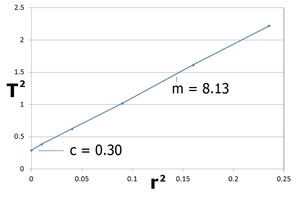
You can see that the graph is a straight line with a gradient of m = 8.13, which we can use to determine the torsion constant N:
N = 8π2M/m = 8π2(0.5)/8.13 = 4.86 Nm rad-1
Note: N will be dependant on the Youngs modulus of the steel being used, its thickness, width and length.
So N will vary for different materails and is very much dependant on the experimental set-up / geometrical arrangement etc.
From the graph the y intercept c = 0.3 can for example be used to estimate the mass b of the bar:
b = 3cN / (π2L2) = 3(0.3)(4.86)/(π212) = 0.44kg
which is close to the measured value of 0.45kg
...................................................
Note 1: A standard pendulum period is T = 2π √(L/g) (L = length of the pendulum in meters and g is the acceleration of free fall 9.8 ms-2) but this is derived assuming the amplitude of the pendulum swing is small i.e. the angle change from vertical θ is small so Sin θ ~ θ. The torsion balance, or torsion pendulum, does not have this restriction and so the equations are more general and can be applied for all motions (assuming of course that the movement is not so extreme that it reaches the elastic limit or fractures the torsion spring etc.).
THE CREATIVE SCIENCE CENTRE
Dr Jonathan Hare, Physics Dept., The University of
Sussex
Brighton, East Sussex. BN1 9QJ.
home | diary
| whats
on | CSC
summary | latest
news