PIC development / experimental unit

Projects developed included: i) a neuron experiment for the Brighton Science Festival (with 8 and 16 independant switch inputs for class participants) as well as controlling lamps, buzzers and providing audio and visual feedback, ii) geiger counter logger system, iii) galvanometer challange, iv) GPS reciever (for Parallax GPS module) as well as many smaller projects and exercises to learn about the PIC and programming etc.
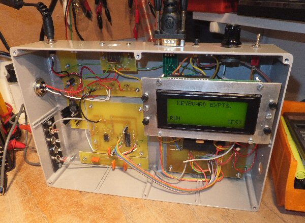
From bottom left (clockwise around the unit):
RS232 connection (additional to the one used for the bootloader)
4 phono (RCA) sockets to make connections in and out of the unit (one shown as an analogue o/p from the DAC)
4 way o/p socket for control, 9V DC input power from SMP
SP2 keyboard input
RS232 bootloader input (just under LCD display)
pot to set the LCD contrast
toggle switch for LCD screen light
4 line LCD display with 4 push switchs around it so that menus can be created and functions set-up
40 pin 16F877 PIC circuit board (bottom right)
0 - 2.5V meter showing the o/p of the DAC (0 = 0V, 255 = 2.5V)
CF card socket (not wired up in this photo)
the left hand pcb is the digital to analogue converter (DAC)
small pcb top left: 5V regulator from the 9V input from the power supply
small horizontal circuit board is a bus bar for 0, 5V and 9V supplies.
THE CREATIVE SCIENCE CENTRE
home | diary | whats on | CSC summary | latest news