A PORTABLE SHORTWAVE RX LOOP ANTENNA
SUMMARY
A simple portable antenna is described that gives good radio reception on the
main shortwave bands.
THE SHORT WAVES
Tuning around the shortwave bands one can hear music, news and stories from
around the
world. The BBC world service claims there are 100 million shortwave sets in
use
today ! The shortwave is still the main way of economicaly broadcasting
world wide.
Although there are many, many different types of shortwave radios avaliable
the
gadgets and gizmos advertised on these sets are often of only minor value.
The real
important part of any receiving system is a receiver of good selectivity
and a suitable
antenna - out of the two the antenna is probably the most important.
A simple homemade receiver costing a few pounds with a good antenna can
out-perform a
three hundred pound set with a poor antenna. The design described here has
been used for
seveal years in a variaty of locations and has performed very well.
ANTENNAS AND LOOPS
Any piece of metal will act as an antenna. When radiowaves pass through a
piece of metal
the electric fields in the wave cause the electrons in the metal to
oscillate which in turn
create voltages (which the radio converts into the sound / programme). A
piece of wire will therefore pick-up all the radio waves that are
present - these may be from local mobile phones, remote control signals,
pagers, local
radio or perhaps short wave signals from the other side of the world !
The antenna will work best, ie. produce the most voltage, when its length
is some fraction,
or multiple, of the size (wavelength) of the radiowaves - the antenna is
said to be resonant.
The simplest antenna is a quarter of a wavelength long (which at medium
wave frequencies is
100m or so long while at short wave frequencies is only perhaps 5-20 m long). Such
an antenna
will bring-in strong signals (provided they are there of course).
Unfortunatly such an
antenna will also bring in a lot of noise and will equaly well pick-up
signals that are
nearby in frequency. The radio will have to cope with these signals - often
with much
degredation of the quality.
One way to improve this situation is to use a loop antenna instead of just
attaching one
end of the antenna to the radio. With the loop you connect both ends of the
wire to the
set - forming a large circle of wire.
If the loop is a multiple of half the wavelength such an antenna works very
well. The
antenna tends to act as a short circuit to frequencies above, or below, the
resonant
frequency and so the antenna appears to pick up far less noise. The only
problem is that
for the short waves, and especialy the medium waves, such an antenna is
realy very large -
impossibly large for most cases !
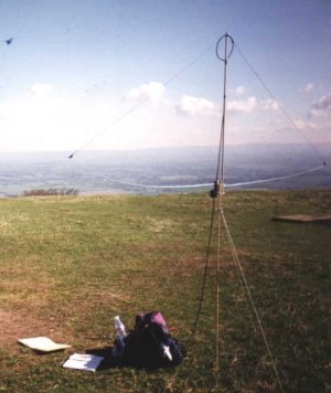
DESCRIPTION OF THE LOOP
The loop described here was based on a design described in Radio
Communication (the Journal of the Radio Society of Great Britain, RSGB) a few
years ago. We describe a small loop which is brought into resonance
(effectively
made 'larger') by use of a tuning capacitor. The loop does not need to be
circular and
this design forms a rough triangle. The signal is tapped-off (coupled)
using a single
turn coil made out of the coax that leads to the radio. To make the whole
thing portable
I have used two telescopic rods as the electrical base of the loop. A wire then goes
from the end of
one of the rods (connections made by crocadile clips), upward to the apex and then
downward to the
end of the other rod. The coupling coil is taped near the top of the loop.
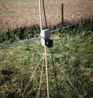
The capacitor
is fixed electricaly (and physicaly) between the two telescopic rods and
wired to the base of each rod.
USING THE LOOP
If your radio has an antenna socket then plug the coax into the set using
the appropriate
connector. If the radio only has a telescopic rod then wind three turn of
insulated wire
around the radio (make sure that it is a battery operated radio - in other
words dont use
the mains) and solder the two ends of this wire to the inner and outer of
the coax.
Tune the radio to a part of the shortwave where you expect to hear signals.
At first the
set will be quite quite. Then tune the loop capacitor slowly until there is
a peak in the
ouput from the loudspeaker. The loop has quite a sharp responce and so you
need to do this
slowly. Fine-tune the capacitor for maximum signal. The loop is directional
and so you can
turn the whole thing to peak the signal (you might need to re-tune the loop
when you move
it) or you can turn it to reduce the signal of an interfering station to
improve the
one you want to listen to.
One rather interesting thing about the loop is that the signal picked-up
will often be much
weeker than with the straight wire. However, the noise picked up by the
loop will be much,
much lower than with the wire and so the signal-to-noise ratio, in other
words the quality
of the signal, will be much better with the loop. Most receivers these days
have plenty
of amplification (often too much) and so the lower signal strengths won't
realy be a problem
in practice.
WHERE AND WHEN TO LISTEN
The type of signal picked up on the shortwave is dependant on the time of
day, the time of
year and of course the frequency. See the stories of science section (coming soon) for
more details of the shortwave or consult some of the books mentioned at the end of this
article. I
would suggest using the loop and finding out for yourselves - its more fun
that way !
As a starter try tuning the radio to about 13-16 MHz and peaking the loop
for these
frequencies. This is a good part of the shortwave to hear signals from all
around the
world around midday and the afternoon. In general the lower frequencies
(1-8 MHz) will be
better at night, or early morning, especially in the winter months. The
higher frequencies
(8-30 MHz) will be best in the summer months and in the day time.
Watch out for unusual conditions on the shortwaves. For example,
there is often a good UK-Australia path around 8 am (GMT) for 30 mins or so each day
for frequencies around 12-16 MHz, this is realy wonderful to hear.
PARTS LIST:
* tuning capacitor: almost any type will do, try: Maplins: FT78K - there
are three wires on this capacitor: connect the outer two together
and use this joint connection and the centre connection for the two wires
that go to the
telescopic rods. Be carefull when fitting fixing screws into the
capacitor.
* two long telescopic rods (Maplins: LB10L) and two screws (Maplins:
JY14Q)
and solder tags (Maplins: BF28F) to suite
* standard RG58 coax (Maplins: XS51F say 5 m) for coupling coil and down
lead to receiver
* small plastic box (Maplins: LH20W) and plastic knob (Maplins: YX04E) for
tuning capacitor
* wooden dowl for the 'mast' and string for guy ropes
* thin standard multicore cable ~5m
* two crocadile clips
* connector suitable for radio receiver
* plastic insulation tape
TOOLS:
hack saw, soldering iron and solder, various screw drivers, sharp knife,
srews,
nuts and bolts etc.
BOOKS AND ARTICLES:
antennas:
The basic design of the loop was taken from the following article:
'A compact hf antenna for portable or base operation', J. R. Killeen
(G3KPV)
Radio Communication, September 1983, p796-797 (Radio Society of Great
Britain)
Other books of interest:
25 simple amateur Band Aerials, E. M. Noll,
Babani Press, 1983, ISBN 0 85934 100 3
An introduction to Antenna Theory, H. C. Wright
Babani Press, 1987, ISBN 0 85934 173 9
Antennas, J. Kraus
McGraw Hill, 1988, ISBN 0 07 035422 7
Experimetal Antenna Topics, H. C. Wright
Babani Press, 1990, ISBN 0 85934 223 9
Practical Antenna Handbook, J. Carr
McGraw Hill, 1994, ISBN 0 07 011104 9
Radio Communication Handbook, Ed. D. Biddulph
Radio Society of Great Britain, 1994, ISBN 1 872309 24 0
the shortwaves and radio stations:
A guide to amateur radio, P. Hawker
Radio Society of Great Britain, 1978, ISBN 0 900612 43 6
(my edition is a bit old now ! ask the RSGB for the latest ed.)
International Radio Stations Guide, Editorial Department
Babani Press, 1985, ISBN 0 85934 130 5
(try to get the latest edition)
International Radio Stations Guide, P. Shore
Babani Press, 1988, ISBN 0 85934 200 X
(try to get the latest edition)
THE CREATIVE SCIENCE CENTRE, JPH, 1999