The Rough Science Meter
The Rough Science Meter
THE ROUGH SCIENCE METER - RS 1 ca. 2000
This was a project that has grown out of one of the inventions from the Rough Science TV series. Here we devised a meter for measuring the power output from a set of seawater batteries. This was one of those lovely experiments done for fun and it just about worked! It's one of my only regrets about the TV work, that on leaving the Island I didn't take the meter back home with me.
A CURRENT METER - HOW IT WORKS
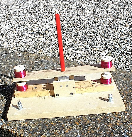
Four coils of wire were made up (about 400-500 turns 2cm diameter). Three were all wound clockwise while one was wound anticlock wise. I made up a simple see saw (a piece of thin wood 3cm x 25 cm) that rested on a heavy wooden base. The seesaw was balanced on the wooden base. This was done using two fine nails fixed to the centre of the seesaw. Also at the centre of the seesaw was fixed a pencil that would form the pointer of the meter. Below this was fixed a small collection of nuts to counter balance the weight of the pointer.
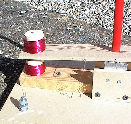
Close up of the Rough Science Meter
One of the 'clock wise' coils was fixed to the end of the sea-saw and to the other end was fixed the anticlockwise coil. Underneath each end of the seesaw, about 1cm below the coils on the seesaw, were fixed the two other clockwise coils of wire. The coils were carefully wired up so that the current would flow through all the coils the same way but in the anticlockwise coil it would flow the other way.
When a current is passed through the set-up a magnetic field is created in each coil. For example, the top of one of the coils may become the north pole while the bottom will become the south pole. The four coils therefore each act as separate magnets. One end of the seesaw has two coils wound the same way and so if the top, of the top, coil becomes 'north' so will the top of the underneath coil. Meanwhile the bottom of the top coil has become south (are you still following me!). The bottom and top coil therefore see opposite magnetic signs and tend to attract one another. The other end of the seesaw has two coils wound opposite to each other and so by a similar argument these two will always repel each other. If one end of the seesaw is attracted to the base while the other end is repelled the seesaw will tend to move in one direction. This will move the pencil pointer and 'hay presto' you have an indication of the current passing in the circuit - you have a current meter! Therefore a current flowing in the coils will cause the seesaw to tilt making the pencil move and acting as our pointer for our ready-made meter.
The seesaw is a bit insensitive! It would have been far better to use two strong magnets on the base and two coils on the seesaw but there you are, one always knows best with hindsight - but it is fun to make a meter with no permanent magnets. However there are some advantages to the meter. Firstly it does not matter which way the current is flowing. So the meter will always read the same way. This means that the meter will work just as well with AC or DC current.
Please, Please, if you have a go at making this meter do not, DO NOT use it on the mains electricity.
Final bit:
It is virtually impossible to get the seesaw to balance on its own. I made up a very simple spring of about five turns using a piece of fine wire wound around a pencil. This was fixed to the base and onto the seesaw (about a 1/3 of the way along from the center pivot) and adjusted so that the seesaw was midway - i.e. the pointer was straight up with no current flowing. By fiddling around with finer and finer springs one can get the meter to be more and more sensitive to current (but also unfortunately sensitive to wind etc.). Also using more turns of wire on the four coils will improve sensitivity. I don't think this meter could detect currents much less than about 1/20 amp but you might do better.
NOTES ON IMPROVING SENSITIVITY
1) try to make the seesaw balanced as best as possible before the spring is attached.
2) make the balance spring from say five turns of very thin wire around a finger or piece of dowel. Stretch the spring so that it is open (i.e. so that it can be compressed or stretched equally well). Fix as close to the centre point of the seesaw as possible.
3) The more turns of wire on the coils the better; use very thin insulated wire. Spiral the ends of the coil wire up and carefully connect them to the other coil windings in a way that does not interfere (much) with the see-saw action.
4) Use as thin as nails as you can get to balance the meter. I used pins/needles on one version that worked well.
home | diary | whats on | CSC summary | latest news