(Note: this article has been published: A simple high temperature light bulb thermometer
J. P. Hare, IOP press, Journal of Physics Education, September 2003, p.378-380 reproduced here by permission of IOP)
Introduction
There are many ways of measuring high temperatures including thermocouples and optical pyrometers. Although these devices are readily available they are costly and can be difficult to explain at GCSE or even A-level. To allow the student to experiment with simple equipment and so get a feel for the science, we need a 'Rough Science' solution to the problem (see 'Notes' section below).
A standard household light bulb has a thin filament made of a high melting point metal (probably tungsten: melting point more than 3000C). When the 240V main electricity passes through the filament of the bulb it heats up and glows so brightly we use it as a lamp. The electrical resistance of the filament varies with temperature, in fact its resistance rises as the temperature rises. This fact alone makes it a good material for a light bulb filament as it means that the current tends to regulate itself when power is applied. The resistance increases as it heats up so limiting the current, reducing the heating effect and stopping it burning out (it is an example of negative feedback which makes a system more stable).
As the filament has such a high melting point it is therefore also a very good material to use as a resistive thermometer and is of course so very easily available.
How it works
We can make use of the filament wires change in resistance with temperature to make a simple thermometer. If we take a standard 100W (240V) mains bulb and carefully break the glass to leave the filament, we can connect the wires to a simple electrical circuit. We can leave the filament on the internal support parts of the bulb and wire it up via the standard mains bayonet connection at the base of the bulb (of course no 240V mains is used in these experiments).
At room temperature the filament resistance will be low, say 40 ohms. At higher temps (eg. from a candle flame or a hand lighter - say 800 C) it rises to 200-300 ohms. As a result the meter reading will change with temperature and we have the basis of a simple high temperature thermometer. Obviously such a simple device has limitations; for example, the filament is fragile and because it is exposed to air it will eventually oxidise. However this simple device is cheap and is almost a disposable instrument for interesting investigations!
The electrical circuit is a simple series circuit consisting of the filament, a 3V battery (eg. 2 x 1.5V AA) , a 10mA FSD current meter and a 1k ohm potentiometer, as shown in the diagram. You can also use a multi-meter (as we did on Rough Science) set to the lowest ohms range (for example 0-1000 ohms).
|
|
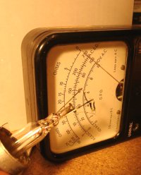
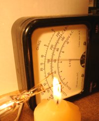
left: filament at room temp with full meter deflection. right: filament probe in candle flame, meter shows corresponding change in reading.
Getting it working and calibration
1) With the undamaged filament suspended in air (ie. at room temp.), wire the base of the bulb to the meter and adjust the potentiometer (or adjust the ohms setting on the multimeter) so that the meter reads a full-scale deflection (FSD). This corresponds to the room temperature reading, say 20C.
2) To test the circuit is working, carefully put the filament into a flame. The meter pointer should move backward towards the 'zero' of the scale as the filament gets hot and its resistance increases.
3) One way of calibrating the meter might be to attach a small piece of wire of a different metal, with a lower melting point, near to the tungsten filament. For example a piece of lead could be twisted to the support of the filament, when it melts the temperature is very near to the melting point of lead (ca. 327C). Other metals give other calibration points. The meter scale will not give a linear in response to temperature and so some careful extrapolation and calibration will be required of the student.
4) If an accurately calibrated thermocouple is available then the two can be placed closely together and comparisons made.
Ideas for experiments and investigations
Ideas for experiments and investigations
There are all sorts of interesting investigations that can be conducted with such a simple thermometer. For example the temperature distribution of a candle flame might be investigated. Also the temperature profile of sunlight brought to focus using a magnifying glass is an intriguing possibility. It might even be possible to probe the invisible infra-red (IR) part of the suns energy which will be refracted to a slightly different spot by the magnifying glass.
As the meter is unlikely to give a linear temperature scale one can use the device to plot lines of equal temperature around a heat source. For example if a metal (melting point known) is used to give a known temperature calibration for the meter then the probe can be moved around a heat source and a plot of this equal temperature profile discovered for the heat source. This way one can get interesting data without having to calibrate the whole meter scale.
This simple disposable device might come into its own for experiments that lead to the destruction of the filament probe. For example when measuring the heat output from a firework or thermite reaction.
NOTES:
1) To safely break a glass bulb put the bulb into a large padded (jiffy) bag as used to send fragile items through the post. Fold over the end and then using a heavy blunt object (eg. a brick) lightly tap the bulb bulge to break the glass. If the bottom of the glass (near to the base) is scored with a glasscutter it will improve the cleanness of the brake. It is advisable that the teacher or technician does this. Open the bag carefully and remove the bulb. If there is still glass attached to the base remove with long nose pliers. Wear protective gloves and glasses / goggles.
2) Lower power bulbs will have a greater resistance and so a 60, or 40 Watt bulb filament will give a greater temperature sensitivity than the 100 Watt, but the filament is thinner and therefore more delicate. Some experimentation might be needed to find the best filament for a particular experiment.
3) This thermometer was demonstrated on the final episode of Rough Science 3 (set in New Zealand, broadcast on BBC World and in the UK on BBC2, Oct 2002). It was successfully used to gauge if the temperature in a home-made furnace rose following the efforts of the group using home made bellows. The idea for this resistive thermometer was finally hit on after much frustrated experimentation with thermocouples and insensitive multi-meters.
4) As with all electrical and high temperature devices, please take extra care when using such a device. Don't go near to mains or mains powered appliances of any kind and be respectful of high temperature and flames.
Websites
1) For details of the Rough Science series go to:
Rough Science web page and also OU web site
2) Sites about temperature and thermometers:
Acknowledgments
I would like to thank all the 'Roughies', directors and producers and especially Steve Evanson for making sure this
little bit of Rough Science never hit the cutting room floor!
Please note that this article has published in Physics Education, Vol 38, issue 4
see Physics Education webpage
home | diary | whats on | CSC summary | latest news