AN ELECTRIC THERMOMETER
In TV3 of Rough Science Kathy and I were to make thermometers and we were happy to help each other on two different types. I chose an electrical device as I thought it might be useful to be able to remotely measure the temp. under lots of insulation while Kathy went for a glass liquid version. The electrical version is described on this web page.
The Balanced Circuit
The balanced circuit is the one,
That makes our modern world run,
In TV's, radios and all manner of things,
This circuit even makes the telephones ring,
Its remarkable in this space computer ages,
That the balanced circuit is still all the rage !
HOW IT WORKS
The electrical thermometer works like this - the design consists of four resistors each made from about 40 meters of very thin (~0.1mm diameter) copper wire. The electrical resistance of wire changes with temperature. It is this change in resistance that causes changes in voltage which we can measure which allows us to use the device to measure temperature.
 Above: Circuit of the bridge thermometer. R are the 4 identical homemade resistors. One is wired into the circuit via a twisted pair of wires so that it can monitor the temp. somewhere else. Ideally the same amount of wire should also be present on the companion series resistor (or alternatively the opposite (left) resistor on the diagram).
The four resistors are wired in what is called a balanced, or bridge circuit. The balance circuit consists of two pairs of resistors wired in series (one after the other) across the battery. The meter is wired between the two mid points of the pairs of resistors.
If each of the four identical resistors are at the same temp. they will each have the same resistance and there will be exactly the same voltage across each. There is therefore no difference in voltage between the two metering points and the meter will not read anything - the circuit is balanced. If however we take one of the resistors and place it somewhere at a different temp. its resistance will change and so the voltage across it will also change, un-balancing the circuit. A voltage difference now exist between the metering points and the meter reads the temp change.
'A back of the envelope', type calculation about the meter thermometer:
I guessed that the resistance of the copper wire we have used for the thermometer should change by about 20-30% between 0 and 100C. Now as each resistor is part of the balanced circuit each will have half of the car battery voltage across it – that's about 6V. So a 20% change in 6V is about 1V. In other words if one of the bridge resistors is used as a thermometer its voltage will change by about this much with respect to the other part of the bridge. I tested the meter I made on a 1.5V battery (from a camera) and it moved about 1cm. When I put the thermometer resistor into hot water the meter moved about 1cm - just what it should have done!! When this type of 'back of the envelope' calculation works out in real life it's a nice feeling.
Making the volt meter
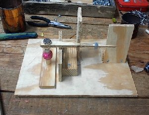
Above: picture of the homemade voltmeter used in the RS thermometer
The meter was designed around a piece of wood balanced on a razor blade. One end has a powerful magnet attached to it (two magnets can be used as they attract each other and hold themselves in place) the other formed a pointer of the meter and also had an adjustable nut to counter balance the weight of the magnet. Below the magnet was placed a 5000 turn coil (we also tried a 1500 turn coil) that Kathy and I made on a piece of dowel so that it could be moved around and positioned to find the spot where the meter would be most sensitive. The two wires from coil formed the electrical connections for the meter. Two delicate springs were made up and fixed above and below the pointer to provide the restoring force to bring the meter back to 'zero' when no voltage was present.
On our first test runs the meter kicked over wonderfully on the car bat. Later on I took a 1.5V battery from a camera and found that the meter moved about 1cm for 1.5V giving a full-scale deflection of about + and - 5V.
Making the resistors
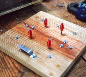
Above: the four identical resistors and the push switch used to turn on the power to the circuit. In use only one of these resistors would be placed in the colder (or hotter) environment.
The coils were wound around a nail for neatness but was done in a special way. Firstly the wire for each resistor is measured out. Then the wire is folded in half so that the two ends are side by side and only then is the wire wound onto the nail. This was done for each resistor. This curious way of winding the coils produces a resistor with no inductance. Inductance is caused by a current flowing in the coil producing a magnetic field but in this case the magnetism is cancelled by the fold in the wire. This speeds up the response of the circuit when it is turned on and off, and when the temp. changes.
SETTING UP AND RUNNING
The main problem with such a simple circuit is that to get good sensitivity we need the full 12 V from the battery. The power flowing through the circuit is enough to heat the resistors ! which is obviously not what we want so a press switch was built into the design so that power was only applied when a measurement was needed to be made. In the mean time the resistors are changing value without the power and so the circuit is ready to run on power on.
The circuit was sensitive enough to detect the extra wire used to connect to the remote sensing resistor and so an extra length of wire had to be added to its neighbouring resistor to balance the circuit to give zero reading (for all the resistors at same temp.).
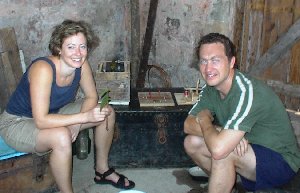
The next step was to calibrate the thermometer. Ellen prepared me some coconut oil, which we put in a small tin can and used to immerse the coil into. This was then put in boiling water. The oil protects the coil windings from oxidation etc. However there were problems with the oil and Ellen slaved over the stove for hours to get me some good oil for this test.

Above: Ellen making up the coconut oil for calibrating the thermometer
SIMPLE CALIBRATION
In principle we have a number of different temperatures with which to calibrate the thermometer: 1) sea water (about 25 C), 2) air temp (about 30 C in the shade at mid day), 3) boiling water (100 C) and also 4) body temp (37 C). we hoped that by using these 'markers' we could get a rough calibration for our thermometers. On our first attempt we only had time to show that the meter reads one way for cooling and the other for heating (with respect to air temp.) so I marked + and – on the meter to show heating or cooling.
Kathy and I tried to calibrate our thermometers with what we had available and the time left. Hers was found to be quite sensitive but mine much wider ranging. We both showed 2 of the many possibilities of making temp. measurements.
THE CREATIVE SCIENCE CENTRE
Dr Jonathan Hare, Physics Dept., The University of Sussex
Brighton, East Sussex. BN1 9QJ
home | diary | whats on | CSC summary | latest news