Described here is a circuit that can decode the 60 kHz MSF time transmission data, calculate the time information and then display it on an LCD screen - a perfect application for a PIC microcontroller. Here we use a 16F877 PIC. Included in this design are 'second' and 'minute' marker LED's as well as the option of displaying the bit A and bit B data as they come in live from the MSF transmission.
PIC BASIC
To program the PIC I used the PDS BASIC compiler from Crownhill [2,3] and the Proton development board [4] to make up the prototype. The Basic Compiler [3] - Proton Basic - is a superb piece of software which I thoroughly recommend. It's a lot easier to write the code for the MSF decoder in BASIC than in assembler language. The Proton development board also provides a simple way of prototyping the versatile PIC16F877. Both the software and the hardware support a bootloader mode. This is a convenient way of downloading a new program into the PIC while still in-circuit [3]. Once you have a working prototype you can then make up a pcb or perf-board version without all the extra stuff that's on the development board (which for this application you don't need) and so you suddenly end up with a really simple circuit that does rather a lot - a classic PIC situation!
The basic BASIC
The program creates an array of 60 (1 bit) variables each element of which is 'filled' with the MSF data as it comes in 'live' from the receiver / detector. The PIC then does the calculations required to convert this data into the time and displays it on the screen (see part 2 of this series). As the PIC operates at 4MHz it speedily does this at the end of the 59 second. Then the whole process starts again for the next 60 bits of data for the next minute.
Time signal data
All the time data we require on the MSF signal is sent two bits at a time every second over the minuet [1]. Although we need most of the bit A data we only need the 58th second of the bit B data as this contains the BST or UTC (GMT) information [1]. click here for details of the MSF time code
The start-bit - MSF carrier off for 500ms
As the time data starts directly after the 'zero' second – the start-bit - it's vital that the programme can reliably detect the i/p going 'zero' for ˝ second. It's worth while making this as robust as possible because if you trigger the data recording at any other time you will only get crazy time results on the LCD screen. In my version the software re-checks the input several times using small delays over much of the period (over ca. 480ms) of the 'start signal'. The program will only continue if all these multiple measurements give a 'set' (zero) response. I also multiply checked the other data bits as they came in. There may well be a better, more efficient way of checking the bits by software but I leave that up to you to create. Once I cracked a reliable way of being sure that the start bit had taken place my software seemed to work ok.
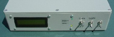
The complete PIC MSF decoder: just the PIC, LCD screen and a few other components.
(MSF receiver not shown, see text)
Leap seconds
I have not built into the PIC program the possibility of dealing with a leap second occurring. Every few years the last minute of the year can have a 59 or 61 seconds. This 'leap' second is designed to correct for the difference between an average day and that based on the Earth's rotation. The MSF signal / data can handle this but I haven't included this as it only effects one (or perhaps in practice two) minutes in the year … and many people won't notice it as they are partying anyway :-).
Polarity of i/p signal
The 60 kHz receiver / detector needs to produce 5V logic level outputs to drive the PIC decoder. If you are using the PLL detector (see the fifth article in this series) the PLL output was inverted so that when the MSF carrier is ON the detector o/p was high (1) while when the MSF carrier drops the detector o/p also drops to zero (0). This is the correct data polarity to drive the PIC decoder. So if the start-bit is received the detector o/p will fall to zero (logic 0) for 500ms producing a zero (0) signal into the PIC decoder for this time. If the MSF data is the wrong logic the PIC won't be able to load up the data and so won't be able to calculate the time (it will just stay in 'waiting for start-bit' mode).
Two display modes
There are two display modes selectable by a front panel 'data' switch:
1) data switch = OFF: shows the basic time information - year, date, time, second and BST / GMT (UTC) information. The second and minute marker LEDs are off in this mode.
2) data switch = ON: as above, but instead of the BST / GMT (UTC) information it will display the bit A and bit B information as it comes in. The second and minute marker LED's will flash at the appropriate times in this mode.
In mode 2 you see the state of the bit A and bit B data coming in 'live' over the minute while in the first mode all this data is hidden. In normal operation you probably don't want to see all this data but it's quite interesting to see and also useful as a 'quality control' of the data while setting up the receiver for example.
Construction
I haven't made any attempt in this version to construct a small space-saving clock; I simply reused a nice painted box from an old project. The circuit is so simple that there should not be any problems setting up the PIC decoder. I have used the 4 connection wiring for the LCD display which is an industry standard Hitachi HD44780 type 2 line display. However I did spend half an hour trying to get the LED backlight on the LCD display to work only to find to my embarrassment that the particular display didn't actually have an LED despite having the connections there!
Keep the crystal and its two capacitors as near as possible to the PIC as possible and fit 0.1uF decoupling capacitors as close to the power and ground connections (between pin 11 and 12). I haven't protected the PIC i/p's to the PIC and you might put 100R resistors in series with the i/p's with 5v6 zener across the pins (to ground) so that any voltages greater than 5V will not harm the PIC. PIC's are easily damaged this way. I didn't bother with a reset switch although I have built in the option on the pcb. Simply turning the unit ON/ OFF will effectively reset the PIC. Without the LED backlight the PIC only takes a few mA but with the backlight ON it takes ca. 100mA.
Using and setting-up
Switching on the PIC flashes the second and minute marker LED's as a system check. The PIC will then display "waiting for start bit". Once you have a receiver picking up the MSF data all ok the receiver o/p needs to go into the PIC decoder.
Once the start bit has been detected the bit A and bit B data gets loaded up once a second into the PIC and these will show on the LCD display if the switch is in mode 2 (the seconds LED will flash every second while the minute LED will flash every 60 seconds). In mode 1 you will simply see the seconds counting up as the data comes in. After the 58 second when the bit B BST / GMT (UTC) data has been read this is loaded up onto the screen. Then after the 59 second the data is used to calculate the time information and is loaded up onto the LCD display.
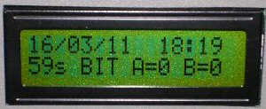
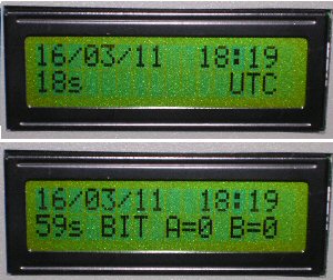
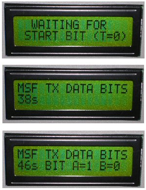
he photo showing the 3 LCD screens you can see i) the initial 'waiting for start bit' mode and the data being loaded up into the PIC after the start bit has been sucessfully detected in ii) mode 1 and iii) mode 2 settings. In the 2 LCD screen picture you see the way the clock looks in mode 1 and 2 respectively once the first lot of 60 seconds of data have been loaded up correctly and the clock is running properly.
Once the time data is on the screen it stays there and is up-dated once a minute. That is unless the data becomes corrupted at which point the PIC will return to "waiting for start bit mode". In mode 1 you see the date, time, seconds and BST / GMT (UTC). In mode 2 you see the bit A and bit B data instead of BST / GMT (see picture with the 2 LCD screens).
Problems
The main problem is making sure that the signal to noise ratio on the receiver is adequate so that the data is 'clean enough' for the PIC to detect. The values of the bit A and bit B data (mode 2) are useful in ascertaining if the data is 'good'. You can go through the example of the time calculation (see part 2 of this series) to see what these values should be and watch them develop on the screen over the minute.
The problem of a clock face
Programming a clock face is harder than you might think. "3 minutes past" is actually "03" not "3". As a result if you simply print out the time on the LCD screen you get "3:3" instead of "3:03". This does not matter much for the hours but for the minutes it looks very odd. The only way I could get over this problem was to first print "00/00/00 00:00" before printing out the time information 'on top' of this. If you print to screen "16 3 11 18 19" (Note the double and single spacing) directly after the screen full of zeros and punctuation you will get the correct looking date and time, in this case "16/03/11 18:19".
Front and back panel
The data switch on the front panel selects the time information mode (1 or 2) and also turns the second and minute marker LED's ON/OFF. There are two sockets at the back for the minute and second marker (5v logic level) o/p's which are only active when the data switch is ON. There is also a socket for the data i/p from the receiver. These expect a logic level input i.e. 5V for "1" and 0V for "0" (carrier off). The back of the case also has the power lead to the 5V (e.g. switch mode) power supply.
Summary
If you build this simple circuit and program in the hex code (I can supply hex code and programmed chips on request) you will have the basis of an atomic standard radio clock for Ł15 or so. You will of course also need a receiver capable of producing logic levels from the MSF signal (see previous articles in this series [5]).