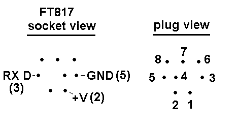
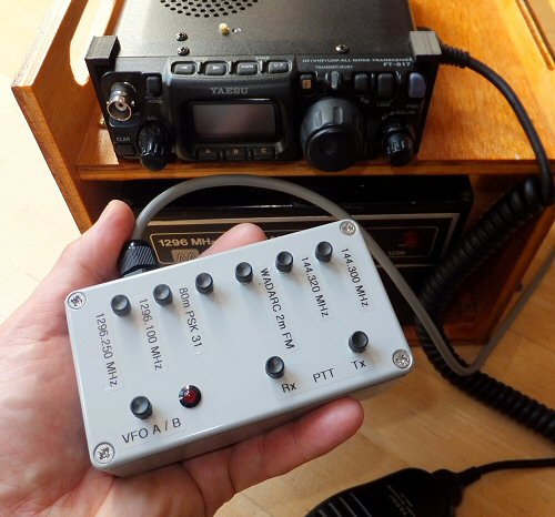
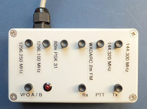
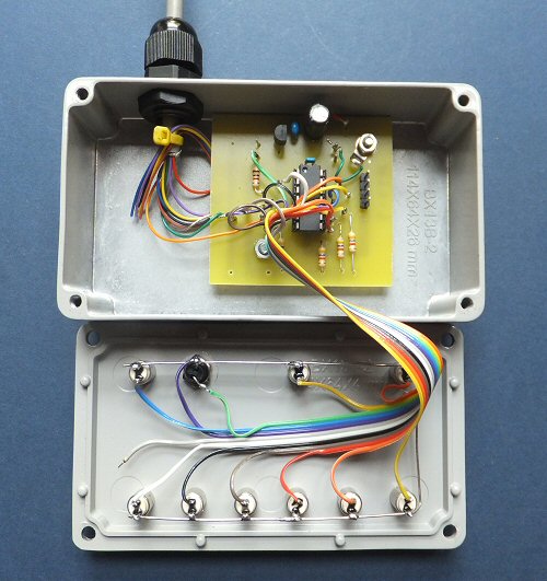
PIC FT817 transceiver controller
published in September 2015 issue of RadCom
Journal of The Radio Society of Great Britain

If I find any bugs, or things that need fixing, I will put up changes and modifications on this page
otherwise please see the original RadCom article for details of this PIC FT817 controller project.


FT817 PIC controller photo

FT817 PIC controller photo

FT817 PIC controller photo


FT817 controller
asm code
FT817 controller
hex code
FT817 controller
RadCom PDF *
PIC keyboard entry
(based on G4JNT project)


* * Note: this article first appeared in RadCom September 2015 and is copyright (c) RSGB 2015 and is used here with permission * *


8-pin min DIN lead and ACC connections to the FT817
I made use of a 2m lead with a 8-pin mini din plug on each end as they go for only a few pounds on e-bay. My intention was to cut the lead in two so then I would have a couple of useful ready-wired leads. However the leads I purchased were a 'cross-over' type so the coloured wires that go to one of the 8-pin plugs do not mirror all the pins of the other plug (see here for more details). The diagram below shows the FT817 socket pins / connections used in this project which include 0V (GND), + V power and the Rx RS232 input to the FT817 (which goes to the RS232 Tx of the PIC):

details of the three 8 pin plug and socket connections used in this project

THE CREATIVE SCIENCE CENTRE


Dr Jonathan Hare University of Sussex, Brighton.
e-mail: j.p.hare@sussex.ac.uk

home | diary | whats on | CSC summary | latest news