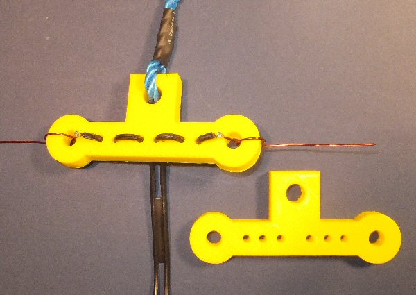
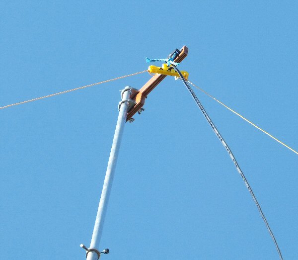
3D printed dipole / inverted-V center
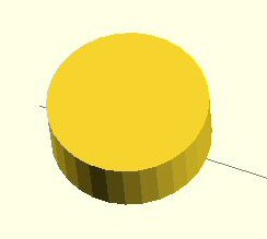
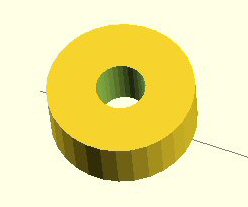
(notes on creating the device using openSCAD code)


inverted V dipole centre


Here is a very simple 3D printed dipole centre that can be used for an inverted-V or normal dipole antenna feed with open wire feeder. Basically the device is a 12mm thick plastic insulator that has two round ends that you can use to attach the dipole antenna wires. Along the length of the insulator I have added six holes so you can feed the split open wire feeder into the middle pair, snaking them in and out of the other two pairs of holes to get a good grip. The two open wire feeder wires are then twisted to the antenna wires and soldered (then covered in sealant). I have also added a hole to fix a rope so you can pull the dipole center up a mast (in the photo I have simply tied it to the mast pully). The yellow filament is good for portable work as it stands out nicely and won 't get lost so easy in long grass. The data sheets I have seen on the 3D printer filaments claim good UV stability so it should be good to make devices for the outside. You can of course use any colour you like but I have found that white plastic (perhaps with TiO2 based pigment) tends not to be UV stable, so it might be worth avoiding this colour filament.

I have written some notes below to explain how this simple device was created using the OpenSCAD software to illustrate how you can create useful things using a 3D printer.

OpenSCAD page

OpenSCAD
documentation
".stl" file
".g" file
".scad" file
my radio
page
my antenna
page
openSCAD code
(doc file)
back to
3D page


inverted V dipole centre


How the dipole center was designed in OpenSCAD

There are many software options for drawing 3D designs. I use openSCAD which is free and easy to learn. It gives great control of parameters such as shape, size angle of solid parts as well as control of bolt hole sizes etc. Once you have designed a 3D object you can save it as a standard 3D .stl file format. We then open this file in a 'slicer' program that will convert the .stl file into a .g file. As the program name suggests this slices the 3D file into thin layers that the printer uses to create the 3D object layer-by-layer. In my machine you simply copy the .g file onto a SD card, put it into the printer and press 'print' on the computer-printer interface. The printer 'homes' and then starts to print out your object. As the printer is controlled by the on-board electronics and SD card files it no longer needs a computer connection and you can leave it to do its job.

Let's look at the design process in a little more detail. To save space I haven't printed out the full code, you can download a text file I have created (from this link) and read through the notes that I have included (if you havent downloaded the OpenSCAD program you can save the .scad file and open it with a text editor such as Notepad).

Creating something like the dipole center is very simple. You could start off by defining the left hand round anchor point using a 'cylinder' command. e.g. cylinder [(h=12, r=15, $fn=30)] will define a cylinder of height (h) 12 mm, radius (r) 15 mm and of resolution $fn = 30. If $fn = 8 say, it would produce a polygon of 8 sides, an octagon. If we use $fn = 30 we get quite a round cylinder. We use 'translate' to place this object a few cm away from the axis center i.e. translate ([x,y,z]). So the code to create a 12mm high, 30mm round (i.e. 15mm radius) cylinder 5cm (50 mm) left from the center will be:

translate ([-50,0,0])
cylinder (h=12, r=15, $fn=30);

series

We repeat this for the right hand anchor point but of course place it the other side of the center (50 instead of -50 for the x co-ord). Then we create a solid block between them using 'cube' and also a section for the rope anchor point (it sits above the center rather than to the side). The 'difference' function in the software allows us to use the 'cube' and 'cylinder' commands to create voids rather than just solids for the rope and dipole anchor points and the small holes for the wires.

The following code will create the round left hand achour point with a 10mm diameter (5 mm radius) hole in it:

//left hand insulator
difference ()
{
//circular wire anchor
translate ([-50,0,0])
cylinder (h=12, r=15, $fn=30);

//center hole
translate ([-50,0,-2])
cylinder (h=12, r=5, $fn=30);
}

series

There are a host of other software commands you can use, as well as mathematical functions so you can create pretty much any shape you might want too.
The complete code can be downloaded in the links above:

"inverted_V_2.scad" file can be opened in OpenSCADE or an editor like Notepad
"inverted_V_2.stl" is a standard 3D format and
"inverted_V_2.g" is the code used by the printer electronics.

THE CREATIVE SCIENCE CENTRE


Dr Jonathan Hare University of Sussex, Brighton.
e-mail: j.p.hare@sussex.ac.uk

home | diary | whats on | CSC summary | latest news