3D printed parts for 7 element I0QM 144 MHz band Yagi
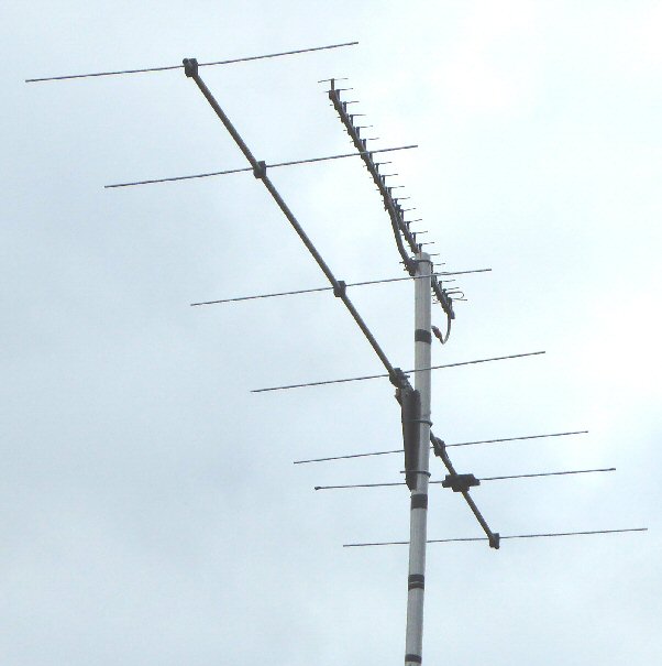
homemade partly 3D printed IQ0M 7 element 144 MHz Yagi below a commercial 23 element 1296 MHz Yagi
I0QM designed the antenna to have a 50 ohm feed impedance at the center of the driven element, so in principle you can directly attach 50 ohm coax. The author suggests using a 1:1 balun (e.g. a bazooka balun). I wont mention any more about the design here as you can get all the details on the link.
I first made a version of this antenna in 2016 and found it had a very good forward gain and good gain bandwidth and 'SWR bandwidth' over the SSB part of the 2m band. It seemed to be almost perfect ... however although it worked great when dry the SWR went high when the antenna became wet after rain.
My prototype used a wooden boom but you will notice that I0QM does not mention anything about the boom material. I have used wooden booms for 2m band antennas in the past with great success (they are cheap, light weight and easy to maintain) so it was dissapointing that I had this problem on what looked like a good design.
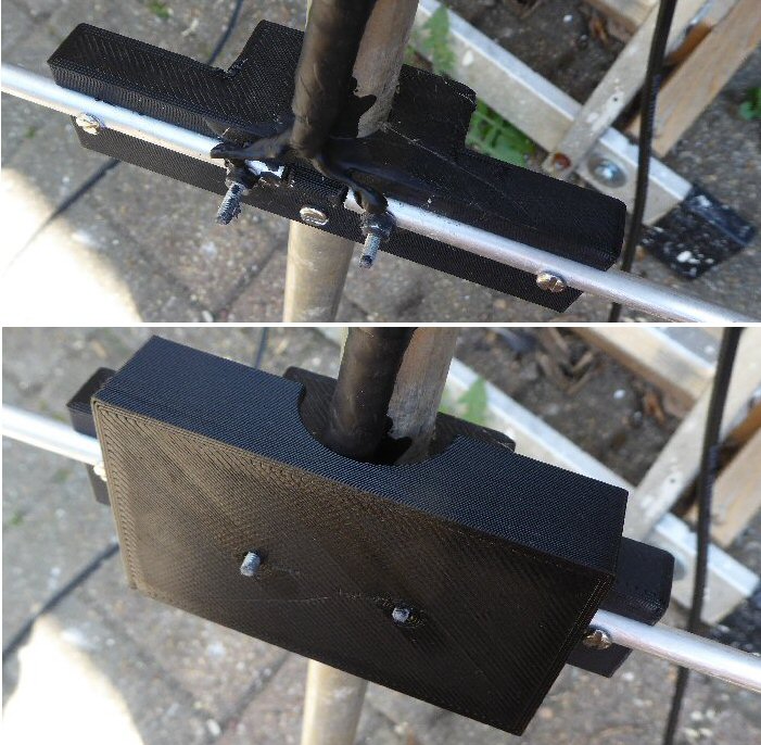
I tried two versions of the dipole center holder. The one used here has an insulating cyclinder, between the two dipole halfs, to try and make sure that any water that falls on this part of the antenna flows away (rather than stay in the cyclindrical gully formed to take the two rods).
A few comments:
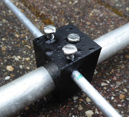
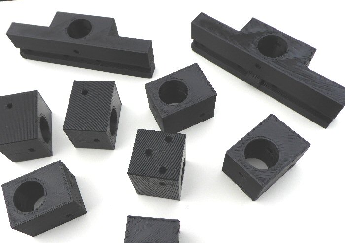
I made my 3D parts for a 18-19 mm diameter aluminum tube / boom as I just happend to have this available. Other boom diameters or a square boom for example could of course be used and the 3D printed parts modified accordingly.
| I0QM 7 element Yagi |
boom fixing: ".stl" file ".scad" file ".g" file |
feed point fixing: ".stl" file ".scad" file ".g" file |
rain hood: ".stl" file ".scad" file ".g" file |
back to 3D page |
THE CREATIVE SCIENCE CENTRE
home | diary | whats on | CSC summary | latest news